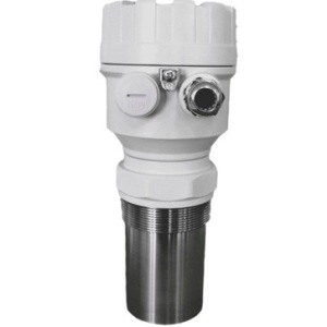
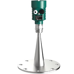
Overview of ultrasonic fluid level sensor
As a non-contact level measuring instrument, the ultrasonic fluid level sensor has the features of high measurement accuracy, easy installation, and basically maintenance-free. Ultrasonic level sensor can also measure liquid level in tanks or containers, also suitable for sewage and corrosive occasions. Ultrasonic fluid level transmitter can also measure the flow of open channel flow meters in combination with flues and weirs. Therefore, ultrasonic fluid level sensor is used in steel, petrochemical, ultrasonic level sensor for sewage tank, water treatment and Water conservancy and many other industries or fields have been more and more widely used, it can be used as ultrasonic fuel level sensor, ultrasonic sensor for water level, ultrasonic level sensor for diesel tank, ultrasonic level sensor for silo, ultrasonic level sensor for solids, ultrasonic fluid sensor level controller.,etc.
Measuring Principle of Ultrasonic fluid level sensor
Generally speaking, the sound wave whose vibration frequency exceeds 20kHz is called ultrasonic wave, which belongs to a kind of mechanical wave. The attenuation of ultrasonic waves in the liquid is very small, so the penetrating ability is strong. The ultrasonic level gauge uses this feature to measure the fluid level.
When the ultrasonic fluid level sensor is working, the ultrasonic transducer (probe) emits high-frequency pulsed sound waves, which are reflected back when encountering the surface of the water to be measured, and the reflected echoes are received by the transducer and converted into electrical signals. The propagation time of the sound wave is proportional to the distance from the transducer to the surface of the measured medium. The relationship between the acoustic wave transmission distance L, the speed of sound C and the transmission time T can be expressed by formula (1):
L=C×T/2 (1)
When the ultrasonic fluid level sensor emits ultrasonic pulses, it cannot detect the reflected echo at the same time. Because the transmitted ultrasonic pulse has a certain time width, and the transducer has residual vibration after the ultrasonic wave is transmitted, the reflected echo cannot be detected during the period, causing the reflected wave and the transmitted wave in a small area under the probe surface to overlap and cannot be identified. , cannot be detected normally, this area is called the measurement blind area. The size of the blind zone is related to the range of the ultrasonic level gauge.
Specifications of ultrasonic fluid level sensor
-
Level range can be measured by ultrasonic level transmitters: 0-4mts, 6meters, 8m,0-12 mts,66 ft,0-30 metres, 40ft.
-
Enclosure: NEMA 4X (IP67);
-
Option with Teflon material ultrasonic level sensor for corrosive fluids measurement;
-
Output and Communications: 4-20mA,RS-485 MODBUS, Profibus-DP,HART protocol;
-
Option with switch and relay outputs, can be with 2,4 and max 6 SPDT, ultrasonic sensor level controller;
-
Power supply: DC 24V or AC 220V;
-
Electronic fluids level sensor with digital display or non-display low price and economical level sensor, the display has 4 digits to indicate level range;
-
Option with Exia IIC T6, intrinsically safe explosion-proof
-
Low price replacement for ifm ultrasonic level sensor, ultrasonic level transmitter Siemens, sick ultrasonic level sensor, flowline ultrasonic level sensor, greyline ultrasonic level transmitter
Installation requirements and precautions of ultrasonic fluid level sensor
-
(1) Flange or threaded installation is generally used when install ultrasonic level sensor, and hoisting is not recommended, because hoisting is easily affected by wind and shakes:
-
(2) The position where the fluid level fluctuates violently, such as the inlet and outlet, should be avoided as far as possible directly below the probe, as shown in Figure 2:
-
(3) Due to the existence of the sound beam angle, the ultrasonic level probe should be installed with a certain distance from the wall or pool wall, as shown in Figure 3:
-
(4) There should be no obstacles within the range radiated by the ultrasonic beam, and the facilities in the pool or container, such as escalators, pipelines, mixers, etc., should be avoided as far as possible during installation:
-
(5) The installation site should be as far away as possible from equipment that is prone to strong electromagnetic interference.
-
(6) Do not install multiple ultrasonic fluid level gauges in the same container to avoid interference with each other and cause measurement errors.
-
(7) For containers with an arched top, the ultrasonic fluid level sensor should be installed away from the center of the tank top to avoid the formation of multiple reflection echoes, as shown in Figure 4;
-
(8) For a conical container with a flat top, the level gauge should be installed in the center of the top as much as possible, as shown in Figure 5:
-
(9) When there is a nozzle on the container and the nozzle cannot be shortened so that the probe emitting surface cannot protrude from the inner wall of the container, or the distance from the probe emitting surface to the highest liquid level is less than the blind area, so that the correct detection cannot be performed, an extension tube should be installed. Perpendicular to the liquid level, the inner wall should be smooth:
-
(10) It should be avoided as much as possible to install in places where the liquid level is prone to accumulation of foam, floating objects or violent fluctuations, because it will affect the echo quality and generate false echoes, thus affecting the measurement accuracy. If necessary, a still-pipe can be installed, and its length can be as long as the minimum liquid level. It should be ensured that the liquid inside and outside the pipe can rise and fall freely and synchronously, and the inner wall should be smooth.
-
(11) Try not to use it in places with water vapor. If there is steam, it is easy to form water droplets and adhere to the surface of the level probe, which will affect the normal measurement.
-
(12) The installation position should avoid strong vibration. If it is installed in a light vibration area, a rubber gasket can be installed to reduce vibration.
-
(13) A sunshade (rain) cover should be installed when installing in the open air.
-
(14) The signal line should be shielded and grounded at a single point.
-
(15) It should be used at the nominal ambient temperature of the ultrasonic fluid level transmitters.
Temperature compensation and sound velocity correction
The relationship between the speed of sound in the air and the air temperature is V=(331.5+0.6t)m/s. From the temperature compensation formula of this speed of sound, it can be seen that the speed of sound is greatly affected by temperature. The influence of the speed of sound is 0.6m/s. At 20°C and 1 standard atmospheric pressure, the speed of sound is about 344m/s. It can be seen that the influence on the measurement error is about 0.17%. When the temperature error exceeds 3°C, the ultrasonic liquid level measurement the error is more than 0.5%. Therefore, the ambient temperature should be measured to correct the speed of sound. In practical applications, an ultrasonic level gauge with temperature compensation function should be selected to overcome the impact of ambient temperature changes on fluid level measurement.
Common fault diagnosis
When a fault occurs during the use of the ultrasonic liquid level sensor, the fault diagnosis can be carried out according to the following methods, so as to deal with it quickly and correctly.
-
(1) Check whether the wire connection is correct.
-
(2) If the liquid level fluctuates violently, consider increasing the damping time appropriately.
-
(3) Whether the surface of the probe is splashed or condensed, thereby blocking the transmission and reception of sound waves.
-
(4) Check whether the liquid level accumulates and floats foam, which will adversely affect the echo.
-
(5) Whether the ultrasonic liquid level enters the blind zone.
-
(6) Whether the power supply voltage is within the nominal range:.
-
(7) Is there any source of interference around the level gauge?
-
(8) Whether the installation is reasonable, please refer to the relevant clauses of this article for inspection and processing.