
HCL (hydrochloric acid) flow meter
Related Products
26GHz Pulse Radar Level Instrument
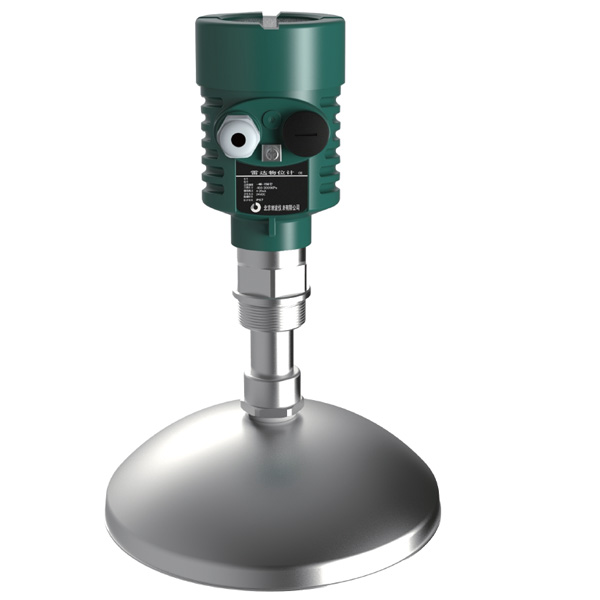
SKRD90 series radar level transmitter is designed to be used as non-contact and continuous level measurement instruments of liquids pulps and bulk solids.
PTFE Diaphragm Seal Pressure Gauge
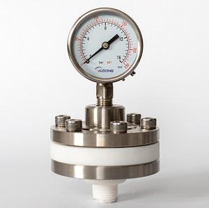
Teflon (PTFE) material diaphragm seal pressure gauge are manufactured for protecting the pressure gauge from strong corrosive medium.
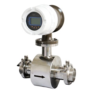
Flow meter type
Electromagnetic flow meter can be used as acid resistance flow meter to measure hydrochloric acid, it is a kind of volumetric & in line flow meter.Principle
Faradays’s law. Formula: E=k*B*D*V. The induced voltage (E) is directly proportional to the velocity (V) of the liquid passing the magnetic field (B). The induced voltage is transmitted to the mag meter converter through the electrode circuit.
You can refer to below table and choose the proper type HCL flow sensor size according to the flow range:
|
Size(DN) |
Pressure |
Min flow range velocity(0-0.5)m/s |
Max Flow range velocity(0-10)m/s |
|
10 |
4.0 Mpa |
(0-2.25)L/min |
(0-45)L/min |
|
15 |
4.0 Mpa |
(0-5)L/min |
(0-100)L/min |
|
20 |
4.0 Mpa |
(0-7.5)L/min |
(0-150)L/min |
|
25 |
4.0 Mpa |
(0-10L)/min |
(0-200)L/min |
|
32 |
4.0 Mpa |
(0-20L)/min |
(0-400)L/min |
|
40 |
4.0 Mpa |
(0-30L)/min |
(0-600)L/min |
|
50 |
4.0 Mpa |
(0-3)m³/h |
(0-60)m³/h |
|
65 |
4.0 Mpa |
(0-6)m³/h |
(0-120)m³/h |
|
80 |
4.0 Mpa |
(0-9)m³/h |
(0-180)m³/h |
|
100 |
1.6 Mpa |
(0-12)m³/h |
(0-240)m³/h |
|
125 |
1.6 Mpa |
(0-21)m³/h |
(0-420)m³/h |
|
150 |
1.6 Mpa |
(0-30)m³/h |
(0-600)m³/h |
In order to make the electromagnetic flowmeter work stably and reliably, the following aspects should be noted when selecting the installation location:
1. Try to avoid ferromagnetic objects and equipment with strong electromagnetic fields (large motors, large transformers, etc.) to prevent the magnetic field from affecting the working magnetic field and flow signal of the sensor.
2. It should be installed in a dry and ventilated place to avoid sun and rain. The ambient temperature should be -20~+60°C, and the relative humidity is less than 85%.
3. There should be plenty of space around the flowmeter for easy installation and maintenance.
4. The HCL sensor can be mounted horizontally and vertically, but it should be ensured that the effects of deposits and bubbles on the measuring electrode are avoided and the axial orientation of the electrode is kept good. When installed vertically, the fluid should flow from bottom to top.

5. The sensor cannot be installed in the highest position of the pipe, which is easy to accumulate air bubbles.

6. Ensure full pipe installation
Make sure that the flow sensor is full of
the liquid hydrochloric acid under test when measuring, and that the non-full
tube state cannot occur. If the pipe is not full or the outlet is vented, the
sensor should be mounted on a siphon.

7. Installation between elbows, valves and pumps
In order to ensure the stability of the measurement, a straight pipe section should be provided before and after the sensor, and the length is given by the following figure. If this is not possible, a stabilizer should be used or the cross-sectional area of the measuring point should be reduced.

8. The sensor cannot be installed in the water inlet of the pump
To avoid negative pressure, the sensor should not be installed in the pump's water inlet, but should be installed in the pump's water outlet.
9. Sensor inlet straight pipe section and outlet straight pipe section
For an ideal installation location, there
should be enough straight pipe sections before and after the measurement point.
The inlet straight pipe section should be ≥5D, and the outlet
straight pipe section should be ≥3D (D is the sensor nominal diameter). The plug-in inlet straight
pipe section should be ≥ 20 D and the outlet straight pipe section ≥ 7D (D is
the sensor nominal diameter).

we will contact you within 24 hours.


