
English
For engine cooling and generator systems with three separate return lines, the right flow meter type depends on the medium. Use a turbine flow meter for the water return line (DN80 / 3-inch, 225-2250 LPM, SG 1.0, 0.75 cP) and the oil return line (DN25 / 1-inch, 26-266 LPM, SG 0.88, 20 cP). Use an oval gear flow meter for the diesel return line (DN15 / half-inch, 1-200 LPH) where viscosity is moderate and flow rates are low. All three support 4-20mA or 0-10V output at 24V DC.
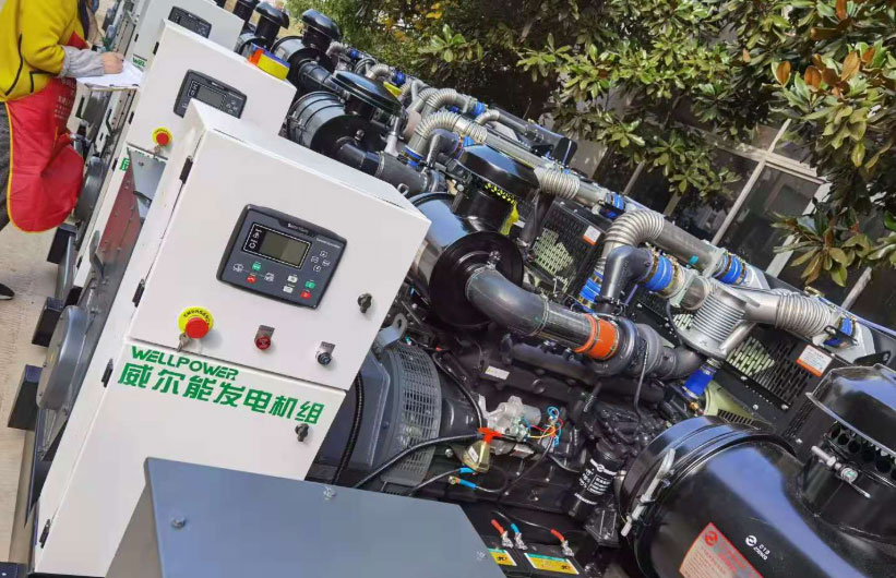
Engine cooling circuits and generator sets typically run three separate fluid return lines back to reservoirs or heat exchangers: a water (coolant) return, a lube oil return, and a diesel fuel return. Each one has a different pipe size, flow range, viscosity, and density. Getting the meter type wrong on any of these three lines is a common source of instrumentation problems on site.
This guide covers how to select flow meters for each return line, what specifications to confirm before ordering, and why turbine meters work on water and oil but oval gear meters are the right call for low-flow diesel.
The water return line carries cooling water back from the heat exchanger or radiator to the sump or cooling tower. Flow rates are high and viscosity is low, typically around 0.75 cP at operating temperature. A 3-inch (DN80) pipe carrying 225 to 2250 LPM is a good fit for a turbine meter: the velocity range is wide enough to give a solid signal, and water is clean enough that the turbine bearings last.
The oil return line is different. Lube oil at 20 cP is roughly 20 to 25 times more viscous than water. That affects meter selection and the valid flow range for turbine meters specifically. A 1-inch (DN25) pipe at 26 to 266 LPM is still within the turbine meter's working viscosity envelope, but only if the minimum flow is not pushed too low.
Diesel return is the most demanding of the three. Flow rates on a diesel return line from an injector or fuel supply circuit are often much lower than people expect: 1 to 200 LPH is a very small flow, and 1 LPH in a half-inch pipe corresponds to an extremely slow velocity. Turbine meters do not spin reliably at that velocity. Oval gear meters do.
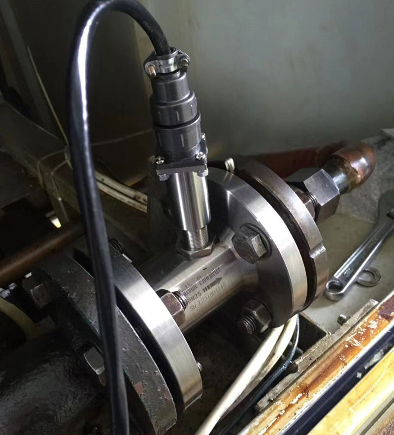
A turbine flow meter measures flow by counting the rotation of a rotor placed in the flow stream. The rotor speed is proportional to velocity, which converts to volumetric flow with a calibration factor (K-factor). For clean water at 0.75 cP and a flow range of 225 to 2250 LPM in a 3-inch pipe, this technology is a natural fit.
The velocity at minimum flow (225 LPM in DN80) works out to about 0.74 m/s. Most industrial turbine meters start producing a reliable signal above 0.3 m/s, so there is adequate margin at the low end. At maximum flow (2250 LPM), velocity is around 7.4 m/s, which is within normal turbine meter operating limits. The turndown ratio here is 10:1, which turbine meters handle without issues.
| Parameter | Value |
| Medium | Water |
| Pipe size | 3 inch / DN80 |
| Flow range | 225 - 2250 LPM |
| Specific gravity | 1.0 |
| Viscosity | 0.75 cP |
| Min velocity at 225 LPM (DN80) | Approx. 0.74 m/s |
| Max velocity at 2250 LPM (DN80) | Approx. 7.4 m/s |
| Turndown ratio | 10:1 |
| Signal output | 4-20mA / 0-10V |
| Recommended meter type | Turbine flow meter |
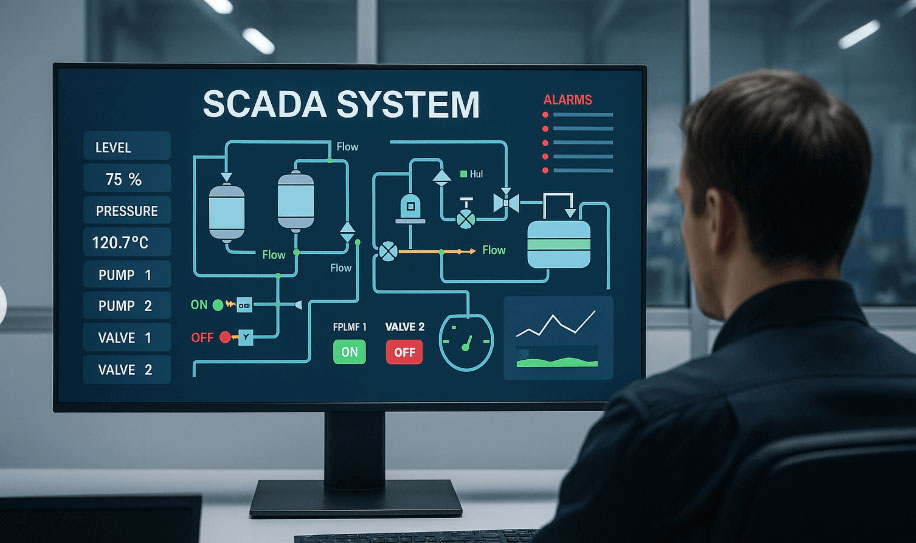
Flow meter SCADA system
Output options are 4-20mA for analog PLC inputs or 0-10V for systems that prefer voltage signals. Both outputs represent the full flow range linearly. For a cooling system where you want to see exact flow rate on a SCADA display or trigger an alarm at low flow, the 4-20mA output is the more common choice because it is less susceptible to voltage drop over long cable runs.
One installation note: turbine meters require 10 pipe diameters of straight upstream run and 5 diameters downstream to keep the velocity profile symmetrical. In a tight plant layout near a pump discharge or a valve, this is the first thing to check before specifying a flanged turbine meter.
Twenty cP is where engineers start asking whether a turbine meter is still the right choice. The answer is yes, provided the minimum flow velocity stays above the viscosity-corrected start threshold. At 20 cP, a turbine meter's low-flow performance degrades compared to water service: the rotor's bearing friction is higher, so it needs a faster fluid velocity to start spinning consistently.
For a 1-inch (DN25) pipe at 26 LPM minimum flow, the velocity at minimum flow is about 0.92 m/s. That is above the practical start threshold for a well-designed industrial turbine meter at 20 cP. The maximum at 266 LPM gives about 9.4 m/s. Turndown is again approximately 10:1.
| Parameter | Value |
| Medium | Lube oil |
| Pipe size | 1 inch / DN25 |
| Flow range | 26 - 266 LPM |
| Specific gravity | 0.88 |
| Viscosity | 20 cP |
| Min velocity at 26 LPM (DN25) | Approx. 0.92 m/s |
| Max velocity at 266 LPM (DN25) | Approx. 9.4 m/s |
| Turndown ratio | Approx. 10:1 |
| Signal output | 4-20mA / 0-10V |
| Recommended meter type | Turbine flow meter |
Process temperature matters here more than on the water line. Lube oil in an engine circuit can reach 80 to 100°C. The turbine meter body material and rotor bearing material need to match. Carbon steel or stainless steel body with tungsten carbide or ceramic bearings are standard for lube oil service. Specifying the wrong bearing material is a common early failure point on oil turbine meters in generator room applications.
If the oil contains particulate contamination (wear metal debris, carbon deposits), a coarse strainer upstream of the turbine meter is good practice. Turbine rotor bearings are not designed to handle abrasive fines continuously.
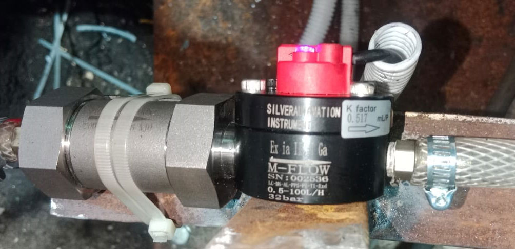
Here is the part most engineers get wrong when they first spec a three-line system. The diesel return flow of 1 to 200 LPH in a half-inch (DN15) pipe looks similar to the other two lines on paper. It is not.
One LPH in a DN15 pipe is a velocity of about 0.0016 m/s. That is far below the minimum start velocity for any turbine meter. A turbine rotor will not rotate at that speed regardless of how well it is manufactured. Oval gear meters work on a completely different principle: two oval-shaped rotors mesh together inside a precision-machined chamber. Each rotation of the rotor pair displaces a fixed volume of fluid. The meter counts rotations mechanically, with no minimum velocity threshold. It works accurately from 1 LPH down to even lower flows depending on the model.
| Parameter | Value |
| Medium | Diesel fuel |
| Pipe size | 1/2 inch / DN15 |
| Flow range | 1 - 200 LPH |
| Specific gravity (diesel) | Approx. 0.82-0.85 |
| Viscosity (diesel at 20 C) | Approx. 2-4 cP |
| Velocity at 1 LPH (DN15) | Approx. 0.0016 m/s |
| Velocity at 200 LPH (DN15) | Approx. 0.31 m/s |
| Turndown ratio | 200:1 |
| Signal output | 4-20mA / 0-10V |
| Recommended meter type | Oval gear (positive displacement) |
The 200:1 turndown on an oval gear meter covers the full 1 to 200 LPH range with consistent accuracy. This is also why oval gear meters are the standard for diesel consumption monitoring on generator sets in data centers, hospitals, and industrial plants across Southeast Asia and the Middle East.
One practical issue with oval gear meters on diesel return lines: diesel can contain air bubbles in the return circuit, especially if the injector back-pressure is low. Air in a positive displacement meter can cause over-reading. Fitting a small air eliminator upstream of the meter removes this error source. Most customers do not do this on the first install and then call back after seeing unexpectedly high readings. We see this regularly on diesel return line projects.
| Turbine Meter | Oval Gear Meter | |
| Measuring principle | Velocity (rotor rotation) | Positive displacement (volume per revolution) |
| Minimum flow capability | Limited by rotor start velocity | Excellent, down to < 1 LPH |
| Viscosity range | Best below 30 cP | Works from < 1 cP to > 1000 cP |
| Turndown ratio | Typically 10:1 to 15:1 | Up to 100:1 to 200:1 |
| Pressure drop | Low to moderate | Moderate to higher at high flow |
| Accuracy | 0.5% typical | 0.5% typical |
| Suitable for water line (DN80) | Yes | Not practical at this flow rate / size |
| Suitable for oil line (DN25) | Yes, at 20 cP | Possible but oversized for 266 LPM |
| Suitable for diesel return (DN15, 1-200 LPH) | No | Yes |
| Signal output options | 4-20mA, 0-10V, pulse | 4-20mA, 0-10V, pulse |
Both turbine and oval gear meters in this application are available with 4-20mA or 0-10V analog output. The choice depends on the receiving end.
4-20mA is the standard for industrial PLC and DCS analog inputs. The live zero (4mA = 0 flow) means a broken wire reads as below 4mA, which triggers a fault alarm rather than looking like zero flow. Cable runs up to several hundred meters are practical without voltage drop error. Most engineers in generator and energy monitoring applications use 4-20mA for this reason.
0-10V output suits shorter cable runs and some SCADA input cards that prefer voltage signals. Signal integrity degrades over long cable due to resistance, so keep 0-10V cable runs under 30 meters where possible. If the control panel is in the same room as the meters, 0-10V is fine.
Some models support both outputs simultaneously or allow switching between them via a dip switch or configuration menu. Confirm this at order stage if the customer wants future flexibility.
Water Return Line (3-inch turbine)
Mount in a horizontal run with the rotor axis horizontal. Allow 10 x DN upstream and 5 x DN downstream straight pipe. Avoid installing downstream of a partially open throttle valve. Fit an isolation valve upstream and downstream for maintenance. Connect 4-20mA signal to PLC analog input; 4mA = 0 LPM, 20mA = maximum LPM as configured.
Oil Return Line (1-inch turbine)
Same straight-run requirements as the water meter. Fit a Y-strainer upstream rated for the pipe size and operating pressure. Confirm bearing material is compatible with lube oil at maximum process temperature. If the return line runs near 80 to 100°C, specify a meter with a high-temperature electronics option or remote transmitter housing.
Diesel Return Line (half-inch oval gear)
Install in any orientation. Fit a fine strainer (100 micron or finer) upstream. Consider an air eliminator if the fuel circuit has low back-pressure or runs intermittently. Confirm the materials of construction: most diesel-service oval gear meters use aluminum body with NBR seals as standard, which is compatible with regular diesel and light fuel oil. For biodiesel blends above B20, specify PTFE or FKM seals instead.
| Line | Flow Range | Pipe Size | Meter Type | Model Series | Output |
| Water return | 225 - 2250 LPM | 3 inch / DN80 | Turbine | TFM series | 4-20mA / 0-10V |
| Oil return | 26 - 266 LPM | 1 inch / DN25 | Turbine | TFM series | 4-20mA / 0-10V |
| Diesel return | 1 - 200 LPH | 1/2 inch / DN15 | Oval gear | OGM series | 4-20mA / 0-10V |
Silver Automation Instruments supplies turbine flow meters and oval gear flow meters for all three return line types from standard stock. Customization options include process connection standard (ANSI / DIN flange or NPT / BSP thread), body material (aluminum, carbon steel, stainless steel 316L), and seal material (NBR, FKM, PTFE).
Request a QuoteTo prepare a quotation for turbine and oval gear flow meters for your water, oil, and diesel return lines, send the following to sales@silverinstruments.com: • Pipe size and connection standard (DN or NPS, flange or thread) for each line • Flow range minimum and maximum (LPM or LPH) for each line • Medium, specific gravity, and viscosity at operating temperature • Operating pressure and temperature • Required output signal: 4-20mA, 0-10V, or pulse • Power supply available: 24V DC or other • Quantity per line and delivery location See the turbine flow meter range and oval gear flow meter range at silverinstruments.com for full specifications, dimensional drawings, and ordering codes. |