English
Like all gas flow measurement applications, compressed air systems use two universal meter installation forms: inline and insertion. Both are widely used in the field, but they differ significantly in measurement accuracy, applicable pipe size, pressure drop, and installation method. Below we will take a closer look at both configurations to help you make a more informed selection for your compressed air metering application.
Before comparing installation forms, let’s have a quick overview of the flow meter technologies used in compressed air service:
In practice, thermal mass flow meters are the most widely used technology in compressed air applications. They measure mass flow directly, respond reliably at low flow velocities, and work equally well from branch line leak detection to main header metering. Both inline and insertion configurations are most commonly implemented as thermal mass instruments. In the rest of this article, we will focus on how each installation form performs in compressed air service.
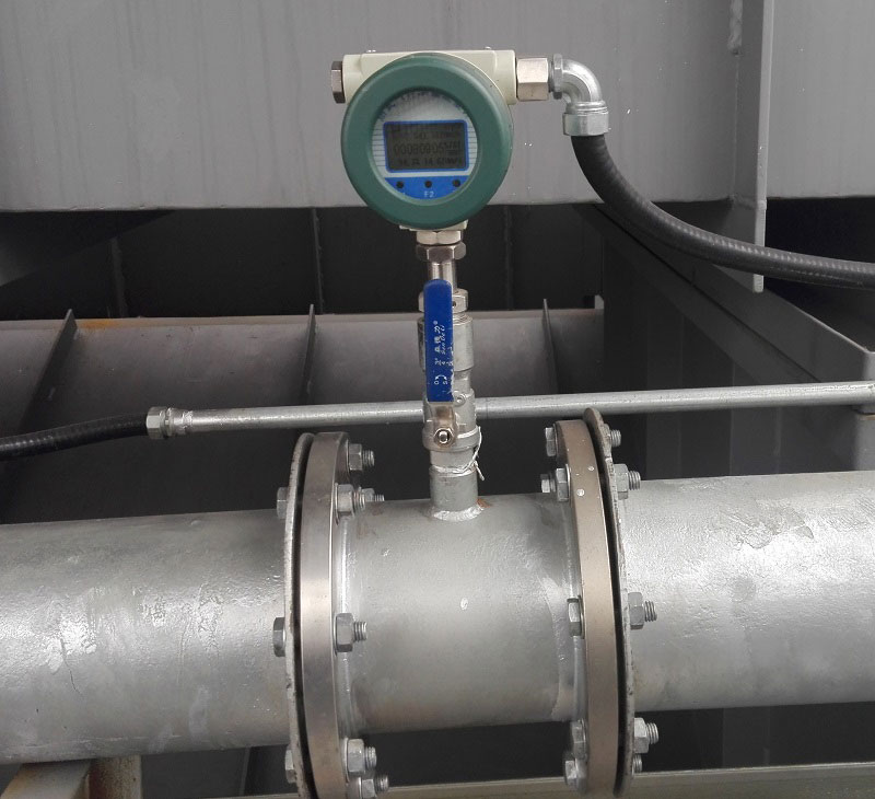
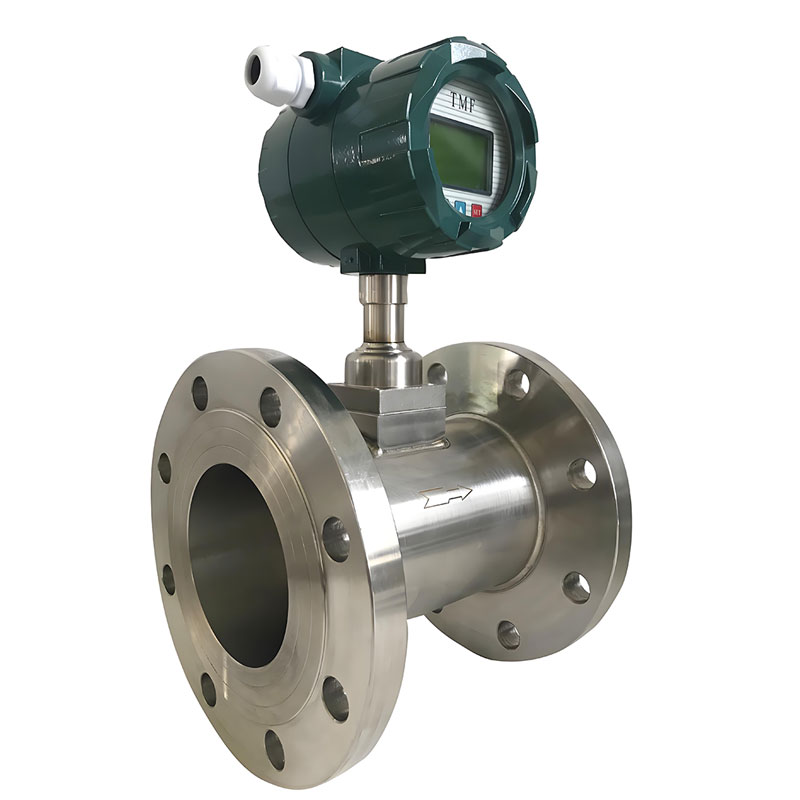
An inline thermal mass meter is installed by cutting into the pipe and fitting the meter directly into the line. All airflow passes through the meter body. Inside, two RTD sensing elements work in tandem: one tracks the gas temperature, the other is heated. The difference in temperature between the two elements tells the meter how much gas is flowing.
Key characteristics:
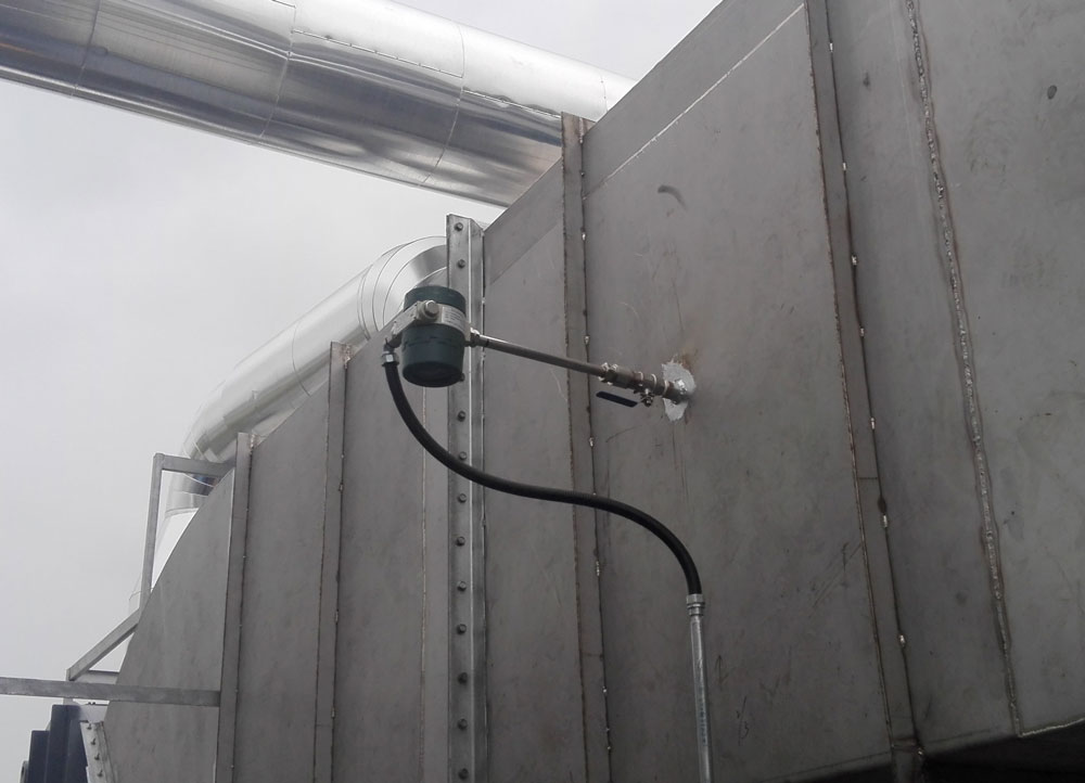
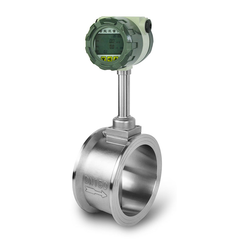
An insertion type thermal flow meter works on the same dual-RTD principle, but instead of cutting into the pipe, a probe is inserted through a hole in the pipe wall to a set depth inside the flow stream. The probe measures local gas velocity and temperature, and the meter calculates total flow from that sample.
There are two probe configurations available:
Key characteristics:
Inline and insertion thermal mass meters differ in one key aspect: the way they measure flow.
Inline meters measure heat transfer across the entire flow cross-section, making them largely insensitive to velocity profile distortion. Insertion types sample at a single point, any upstream disturbance, such as elbows, reducers, partially open valves, or tee junctions can skew the reading.
Selection guidance:
| Pipe size | Recommended type | Rationale |
| DN15–DN80 | Inline thermal mass | Full-bore accuracy, cost-effective at small diameters |
| DN80–DN100 | Inline or insertion | Evaluate based on accuracy requirement and budget |
| DN100–DN300 | Insertion (single-point) | Significant cost advantage over inline |
| DN300+ | Insertion (multi-point averaging) | Multi-point compensates for profile variation at large bore |
A full-bore inline thermal mass meter for a DN300 header can cost five to ten times more than a comparable insertion probe. At DN500 and above, full-bore inline thermal mass meters are generally unavailable or impractical, making insertion the only viable option.
Installation method is another area where inline and insertion meters differ significantly.
Inline meters require cutting the pipe and installing a flanged spool piece, which mandates a full system shutdown and depressurization.
Insertion meters offer more flexibility:
Pressure drop refers to the loss of pressure as compressed air passes through a flow meter. The higher the pressure drop, the harder the compressor has to work to maintain system pressure, and the more energy is consumed.
Inline thermal mass meters typically introduce 20 to 50 mbar of permanent pressure drop at rated flow. Insertion probes, occupying less than 5 percent of the pipe bore, stay below 5 mbar under most operating conditions.
For small pipe sizes, this difference is manageable. For large-diameter headers with high flow volumes, pressure drop becomes a real operating cost, and insertion meters offer a meaningful advantage in this regard.
As discussed above, neither configuration is universally better. The right choice depends on pipe size, accuracy requirement, and site conditions. In most compressed air systems, both meter types have a role to play: inline meters at critical measurement points where accuracy matters most, and insertion meters on larger headers where cost and installation flexibility take priority.
Specify inline thermal mass when:
Specify insertion thermal mass when:
we will contact you within 24 hours..