English
In this article we will introduce the basic principles of 6” electromagnetic flow meters and their usage in the water supply industry. And based on the actual usage situation at Water Supply Association, a detailed discussion was made on the installation, use, and maintenance of 6 inches electromagnetic flow meters.
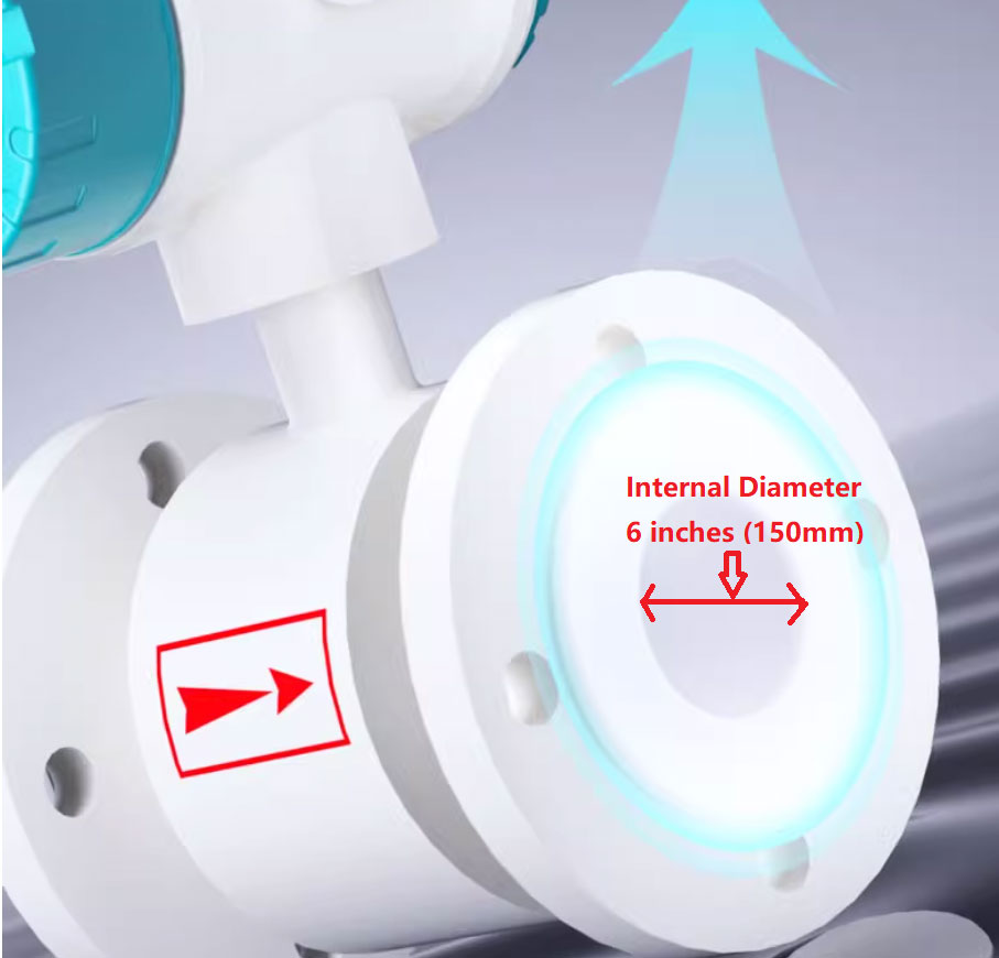
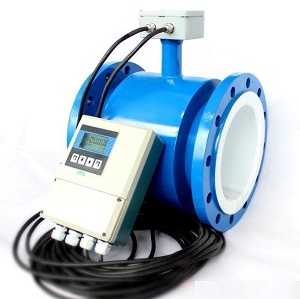
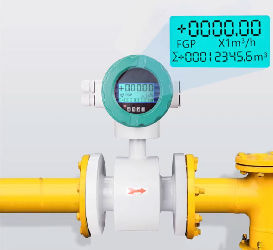
6” magnetic flow meter with ID 6 inches or 150mm
6" electromagnetic flowmeter refers to an electromagnetic flowmeter with an inner diameter of 6 inches (150mm) in the pipe. This 6-inch large-diameter electromagnetic flowmeter is often used to measure sewage, raw water, drinking water, well water, seawater, etc.
In recent years, with the continuous improvement of automation technology in the China water supply industry and the requirements for trade settlement measurement, 6 inches electromagnetic flow meters have been increasingly widely used and promoted, especially in water supply industry where 6 inches electromagnetic flow meters have been widely recognized.
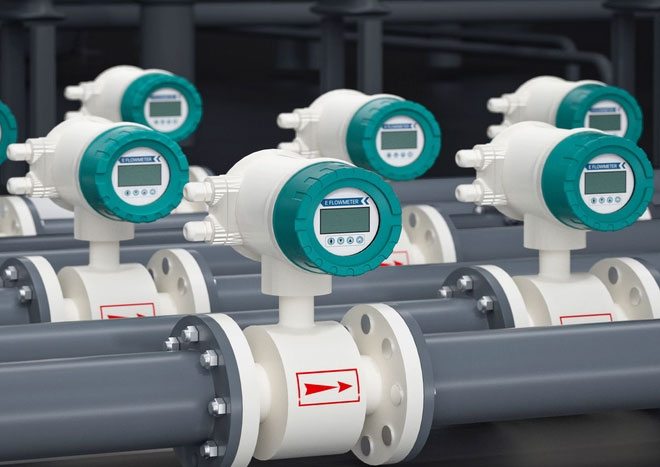
6” magmeter is widely used in water industry
According to Faraday's law of electromagnetic induction, when a conductive liquid cuts magnetic field lines in a magnetic field, an induced potential is generated in the conductor as shown in the figure. The magnitude of the induced potential is proportional to factors such as magnetic induction intensity and the strength of the fluid cutting magnetic field lines.
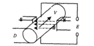
Figure 1 Schematic diagram of induced potential generation
The potential is given by the following equation
E=K*B*V*D
In the formula:
E - Induced voltage
K - Instrument constant
B-Magnetic induction intensity
V-average flow velocity
D-Measuring the inner diameter of the tube
When flowing fluid, the fluid flows through a magnetic field perpendicular to the flow direction, and the flow of conductive liquid induces a voltage proportional to the average flow velocity or unit volume flow rate. Therefore, as long as the measured water has the minimum conductivity, its induced voltage signal is detected through two electrodes in direct contact with the liquid, transmitted to the amplifier through a cable, and then converted into a unified output signal.
we will contact you within 24 hours..
① Due to the fact that the DN150 magnetic flow sensor measurement results are independent of physical parameters such as pressure, temperature, and conductivity of the liquid, the measurement accuracy is high and the work of 6 inches magnetic inductive flow meter is reliable.
6” magnetic flow meter provide reliable operation
② There is no obstruction in the 6 inches measuring tube, so there is no additional pressure loss, that is, there is no additional head loss for measuring water.
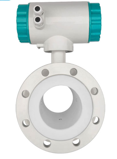
Full bore design of 6” magnetic flow sensor
With the inner diameter of the sensor matching exactly the inner diameter of the pipeline with nothing blocking the flow path, the full bore design ensures the fluid passes through freely at the same diameter, nothing slows it down or creates turbulence, resulting in zero pressure loss and no risk of buildup or blockage.
③ Only the pipeline and electrode come into contact with the measured liquid. Therefore, as long as the electrode material is selected reasonably, the requirements for corrosion resistance and wear resistance can be achieved. 6” magnetic flow sensor has the characteristics of long service life and low maintenance requirements.
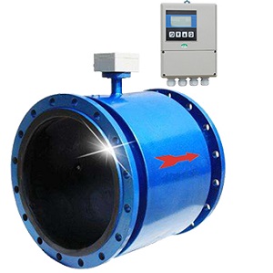
④ 6” Electromagnetic inductive flow meter can measure the flow rate of forward and reverse fluids.
Bi-directional flow measurement by DN150 Electromagnetic Flowmeter
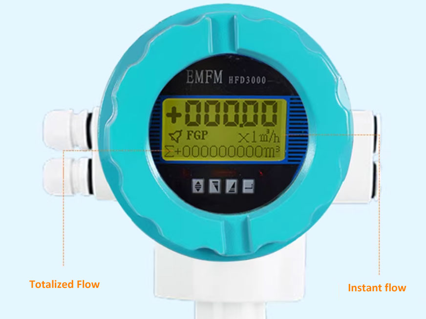
⑤ the output signal is relatively flexible. The 6 inches electromagnetic flow transmitters has output such as pulse, current, frequency, etc.
① The upstream pipeline of the 6” electromagnetic flowmeter has a straight pipe section at least 5 times the diameter length, and the downstream pipeline has a straight pipe section at least 3 times the diameter length. If conditions permit, relax the length of the straight pipeline before the flowmeter to be more than 10 times the diameter of the pipe.
② In the installation of 6 inches magenetic flow sensors, the sensor grounding ring should be reliably grounded, and the grounding resistance should not exceed 10 Ω.
③ Attention should be paid to avoiding external electromagnetic interference, especially interference from power frequency electromagnetic fields, in the selection of usage environments.
④ For situations where valves, especially butterfly valves or right angled bends, are installed outside the front distance in the upstream pipeline of the DN150 flowmeter and seriously affect the flow characteristics, it is best to install rectifiers in a straight pipe with a diameter of 5-10 times the diameter upstream of the flowmeter to achieve stable water flow and improve measurement accuracy.
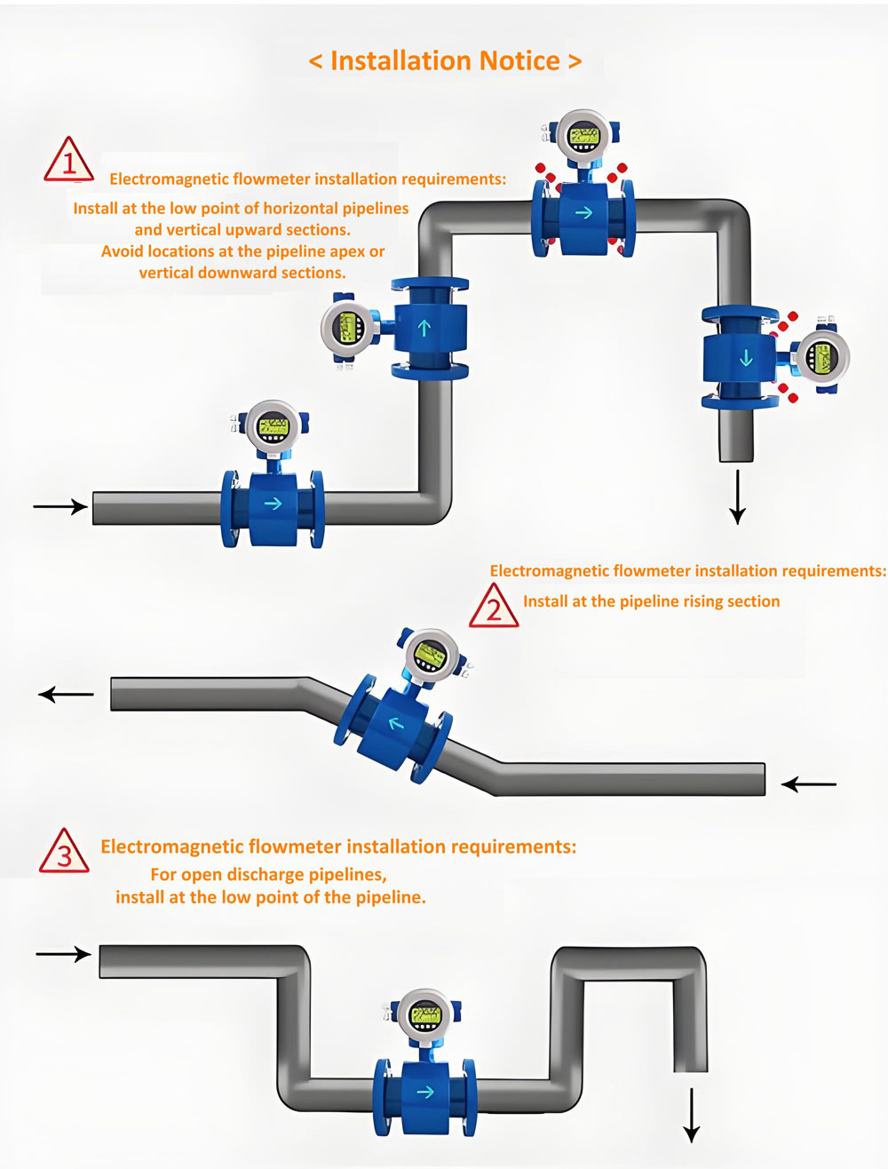
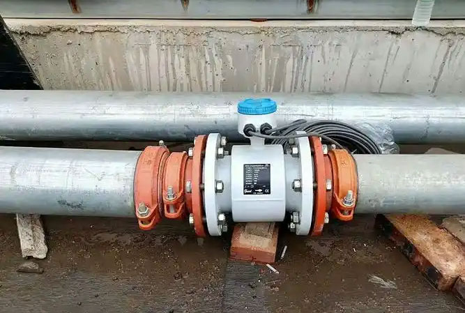
6 inch magnetic flow meter installation
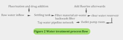
The schematic diagram of the water treatment process principle commonly used in various regional water companies in Shanghai is shown in Figure 2.
Based on the measurement principle and characteristics of 6 inches electromagnetic flowmeter, it has become a widely used product in the water supply industry. Since the first electromagnetic flowmeter was used in China,more and more DN150mm magnetic flow meters are used. 6 inches magnetic flow meters are mainly used for trade measurement of raw water in water plants, alum measurement, backwash water volume measurement, single tube measurement of outlet pump room, plant water measurement, and trade measurement of factory water main pipes. There are also regional companies' pipeline network connection boundaries used for mutual water supply trade measurement.
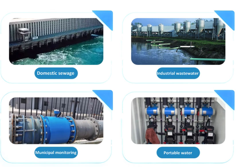
Different water measurement by 6 “magnetic inductive flow meter
Due to the low corrosiveness and abrasion of water quality, in addition to using scraper electrodes for raw water and platinum electrodes for alum metering, rubber lining and stainless steel electrodes are generally used to meet measurement requirements.
The 6 inches magnetic flowmeter has been calibrated in the factory when it leaves the factory. However, once used on site, due to environmental conditions, fluid characteristics, and instrument malfunctions caused by damage to components, it is necessary to conduct a routine on-site calibration for 6 inch flow meters before their initial installation and operation or after long-term use.
Due to the installation of the 6 inches flow sensor of the electromagnetic flowmeter in the water supply pipeline, it is difficult to remove and send it to the laboratory for inspection. Currently, within the scope of flow measurement, there are no regulations or other regulatory documents for online inspection of large-diameter flowmeters under on-site conditions at the national and local levels. In order to ensure the accuracy and reliability of electromagnetic flow meters during initial installation, fault repair, and long-term use without affecting the daily supply of tap water, our company formulated the "Electromagnetic Flow Meter Inspection Regulations" in 1995 as part of our internal measurement management standards. After several years of on-site inspection, exploration experience, and continuous improvement, our company passed the ISO9002 quality management review in 1998 and has been promoted and applied in the city's raw water and various regional companies' water plants.
Reliable operation of 6” magnetic flow meter
① The safety insulation test of the excitation coil of the electromagnetic flowmeter should be greater than 20M Ω.
② The copper resistance test of the excitation coil of the electromagnetic flowmeter should be the same as the original factory value (when the ambient temperature is the same).
③ Test the ground resistance of the electromagnetic flowmeter sensor electrode. If the resistance value is between 2-20k Ω and accompanied by charging and discharging phenomena, and the resistance of the two electrodes is similar, it is considered good.
④ Test the excitation current of the electromagnetic flowmeter converter and observe the value of its output compared to the original current of the converter, with an error not exceeding ± 0.25mA.
⑤ Test the analog output and frequency output of the electromagnetic flowmeter converter, observe its linear changes, and calculate its maximum linear error, which should not exceed ± 0.5%.
⑥ For electromagnetic flow meters with a diameter of over DN1200mm, the push stage NB should be tested, and the current error should not exceed ± 2mA.
Through online inspection of DN150 electromagnetic flow meters, we can promptly and accurately detect whether there are faults or hidden dangers in the electromagnetic flow meters, providing reliable basis and guarantee for ensuring the correct measurement of electromagnetic flow meters, which is beneficial for better management and use of electromagnetic flow meters in the future.
6 inches electromagnetic flow meters have high stability, and the instrument equipment itself generally rarely malfunctions. However, due to changes in environmental conditions or limitations in installation conditions, some problems or malfunctions have occurred that should be resolved or avoided, mainly manifested as the following situations:
① The installation conditions for flow meters have not been met. 6 inches magnetic flow meters have high requirements for the straight section of pipelines, which can be met as much as possible in the design of new water plants. However, for the renovation or installation of old water plants, the above conditions become almost stringent. This affects the stability of the measurement. The solution is to install rectifier tubes to improve the flow characteristics.
② The flow rate of the water being measured is too low, which affects the accuracy of the measurement. Especially for flow meters installed at the boundaries of some areas, 6 inches magnetic flow meter flow range is 30-600 m3/h , if the flow is too low , the low flow rate is caused by the small pressure difference at the end of the regional company's pipeline network. The solution is to open the valves on both sides of the boundary as much as possible.
③ There is gas in the DN 150 pipeline water, causing significant measurement fluctuations and affecting stability. The solution is to find the source of gas and solve it, and if necessary, install exhaust valves in the pipeline.
④ The sensor electrode surface of the 6 inche water flowmeter installed in the raw water pipeline is contaminated by sediment deposition, which affects the measurement. The solution is to use scraper type electrodes and regularly maintain and clean them.
⑤ Lightning strikes caused damage to the converter of the 6 inches magnetic flowmeter, making it impossible to measure. The solution is to install corresponding lightning arresters at the signal input end, excitation current input end, and working power supply end of the converter.
⑥ The accumulation of foreign objects in the inlet pipeline of the 6 inches mag meter causes a sudden change in the flow characteristics of the measured water, which affects the measurement accuracy and leads to significant errors. The solution is to promptly remove foreign objects accumulated in the pipeline.
In short, the high measurement accuracy, good stability, and wide applicability of 6” electromagnetic flow meters provide strong technical guarantees for water plants to achieve automated control and fair trade measurement, playing a huge role. In the future, with the continuous improvement and enhancement of technology, application, and cost-effectiveness, 6 inches electromagnetic flow meters will be increasingly widely used in the water supply industry.