
English
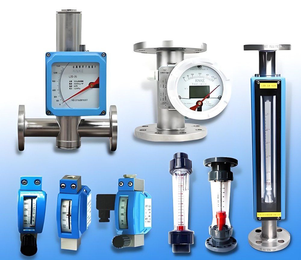
Rotameters, also known as variable area flow meters (VA flowmeter), represent one of the most versatile, long histroy and widely used flow measurement technologies in industrial applications. With numerous models and configurations available on the market, understanding the different types of rotameters and their classifications is essential for selecting the right flow measurement instrument for your specific application.
This comprehensive guide explores how standard and specialized rotameter (variable area flow meter ) models can be categorized from multiple perspectives, helping engineers and procurement professionals make informed decisions for their flow measurement demands.
Standard and specialized flowmeter models available on the market:
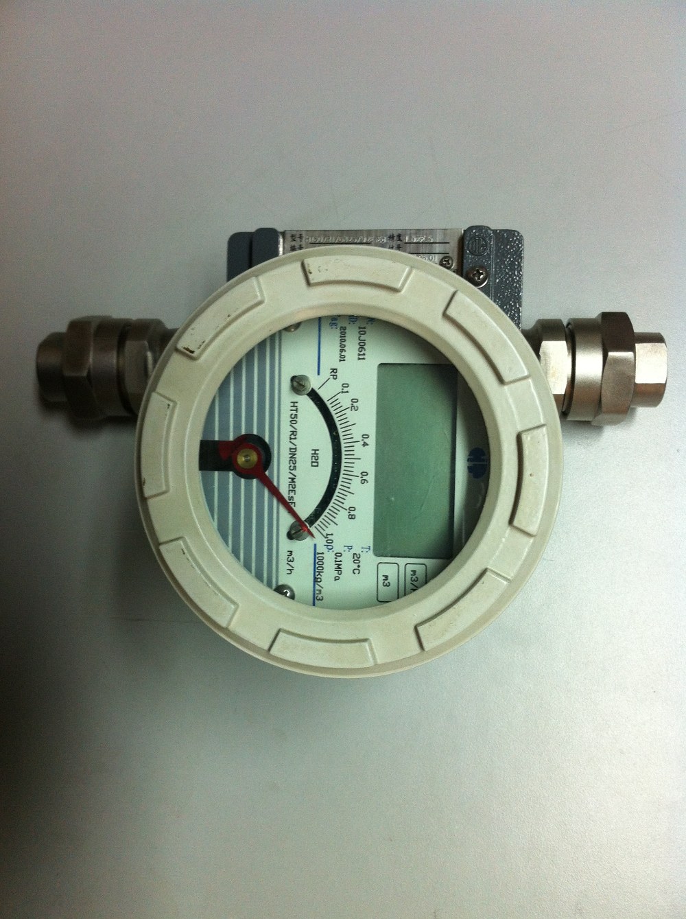
Rotameters with digital reading also with remote signal output
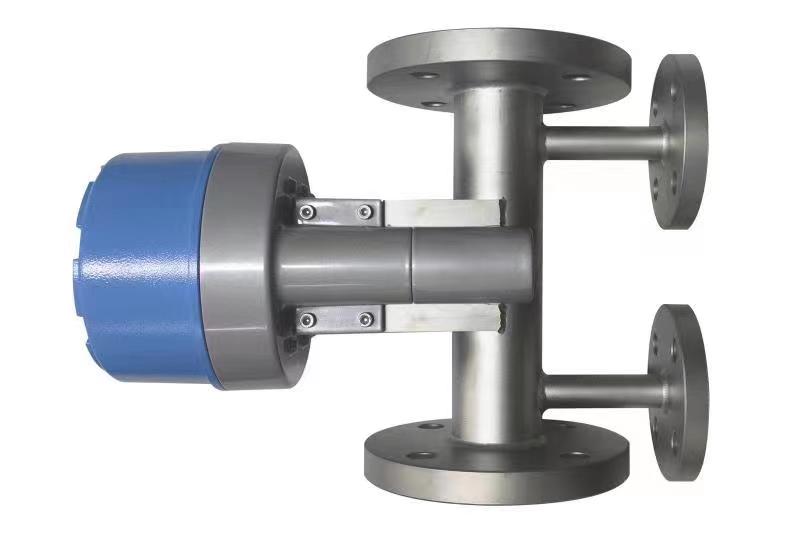
Rotamters with heating jacket
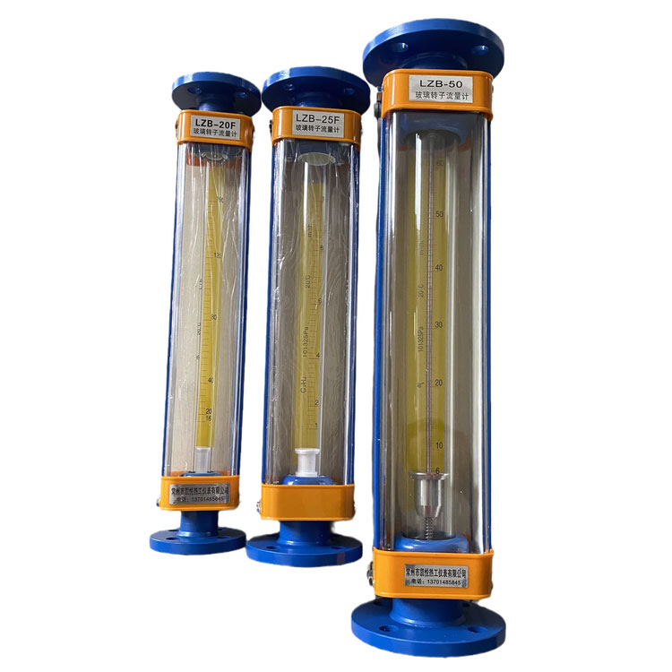
Glass tube rotameters are cheap and widely used
The most commonly used material for transparent tapered tubes is glass. In gas measurement applications with non-guided float designs, improper operation may cause glass tube breakage. Alternative transparent engineering plastics include: polystyrene, polycarbonate and PMMA (acrylic). These materials offer superior impact resistance compared to glass. Certain engineering plastics additionally resist corrosive media that attack glass, including fluorine gas, hydrofluoric acid concentrated alkalis. For specialized applications, quartz tubes are also employed.
The tapered tube interior features two variants: smooth conical surface and guiding ribs/flat surfaces (profiled design). Internationally, profiled tubes with guiding ribs/flat surfaces are available for diameters below 6mm. As shown in Figure 1, the proximity between the float reading position (i.e., maximum diameter point) and guiding ribs/surfaces allows observable readings even with opaque liquids. The ribs/flat surfaces replace central guide rods to prevent float oscillation and eliminate mechanical wear.
The transparent straight-tube rotameter represents a modified design derived from glass tapered-tube rotameter, featuring an orifice plate and tapered float plug as its flow sensing components.
Key advantages include:
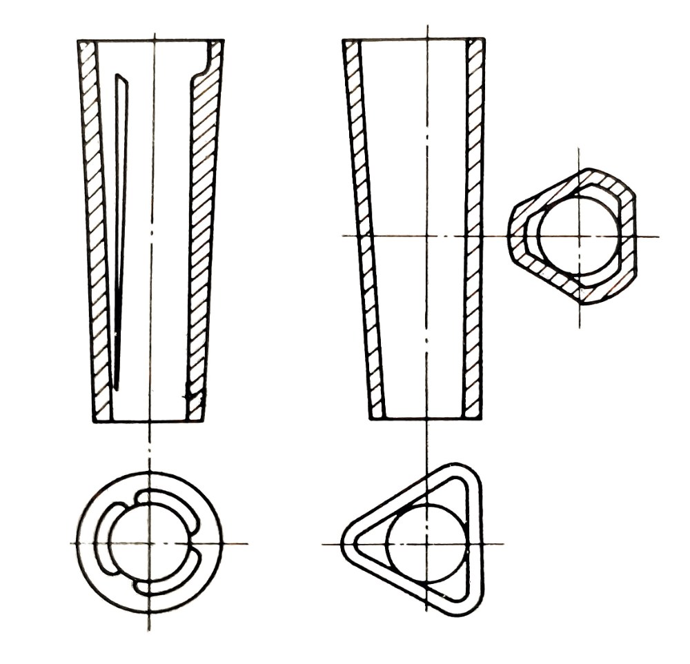
Figure 1: Special-shaped pipe with triangular ribs and three-plane guide
(2) Metal tube rotameter
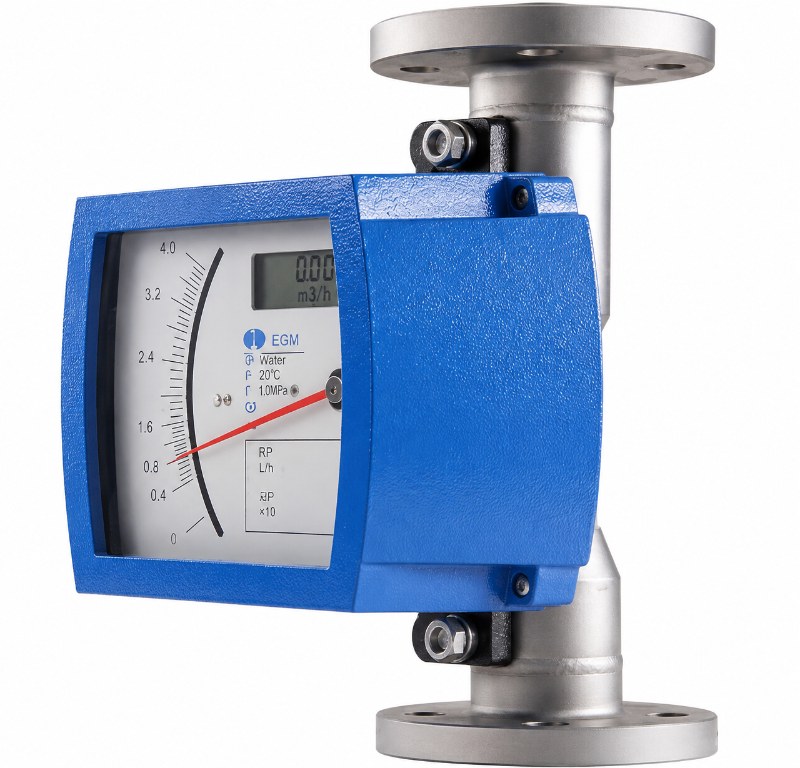
Metal tube rotameters are more robust than glass tube
Compared to glass tapered-tube rotameter, metal tube rotameters offer higher temperature/pressure tolerance for process media and eliminated risk of tapered tube breakage (inherent to glass tube designs).
Metal tube rotameter typically feature either monolithic construction with the tapered tube and housing formed as a single unit, or modular construction where the tapered tube is inserted into the housing. To change the flow specification, simply replace the conical tube with a different cone angle, which is more convenient to use.
In addition to standard configurations, several specialized variants exist:
1) Direct-reading type The most basic design utilizes a transparent straight tube and float plug (or float extension rod tip) for direct visual float position reading.
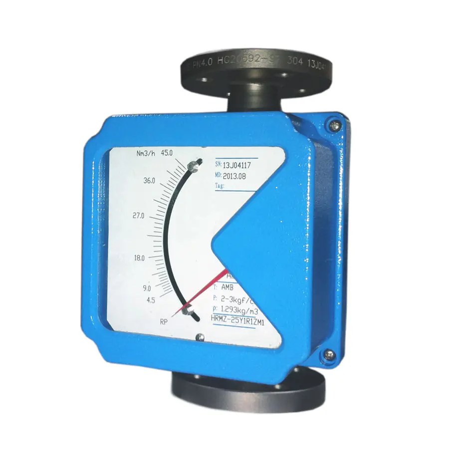
Direct –reading metal tube rotameters
2) Horizontal installation type Specifically engineered for horizontal pipeline mounting
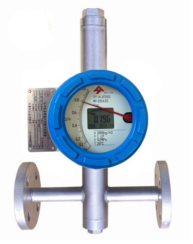
3) In-line type The straight-through type features a fluid flow direction that differs from the typical structure, eliminating the need to alter the flow path. It can be directly connected to vertical pipelines without modifying the piping system, offering simple and convenient instrument installation. This design is increasingly trending toward replacing the traditional right-angle installation structure.
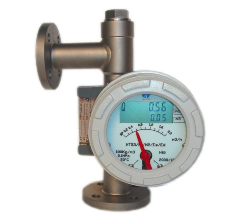
Bottom in and left out rotameters
4) Float plug-orifice type The flow detection element uses a floating plug orifice plate instead of a tapered tube with a float. To change the flow rate specification, simply replace the floating plug with one of a different taper angle, making the process relatively convenient.
Glass tapered-tube rotameters fall under the local-indicating category. While primarily designed for on-site visual indication, certain models are equipped with proximity switches to provide alarm signal outputs for upper/lower flow limit monitoring.
Some local-indicating metal-tube rotameters share identical exterior designs with remote signal output models, differing only in their use of magnetic coupling to transmit float displacement. This displacement is then processed through linearization mechanisms (e.g., linkage-cam assemblies) for local indication.
Purge flow metal tube rotameters employ a distinct design featuring magnetic ring sliders mounted externally on the tapered tube wall. These sliders track float movement while maintaining pressure resistance up to 25-30MPa.
Remote signal output instruments convert float displacement into either electrical current (e.g., 4–20 mA) or pneumatic pressure (e.g., 20–100 kPa) analog signals, corresponding to electrical transmission rotameters and pneumatic transmission rotameters, respectively.
Electrical transmission rotameters are further categorized into standard and explosion-proof models.
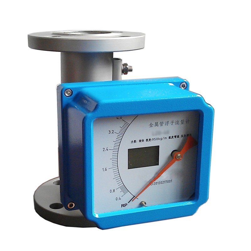
Rotameters with 4-20mA output
Choosing the Right Connection Type for Your Application
Metal tube rotameters are generally equipped with flanged connections, with only a few models using threaded connections, such as high-pressure blow-through type instruments. Glass tube rotameters commonly feature the following three connection methods:
1) Flexible hose connection – Commonly used for instruments with a diameter below 10 mm and in low-pressure applications.
2) Threaded/screw connection – Typically used for instruments with a diameter below 40 mm, though its application is not widespread.
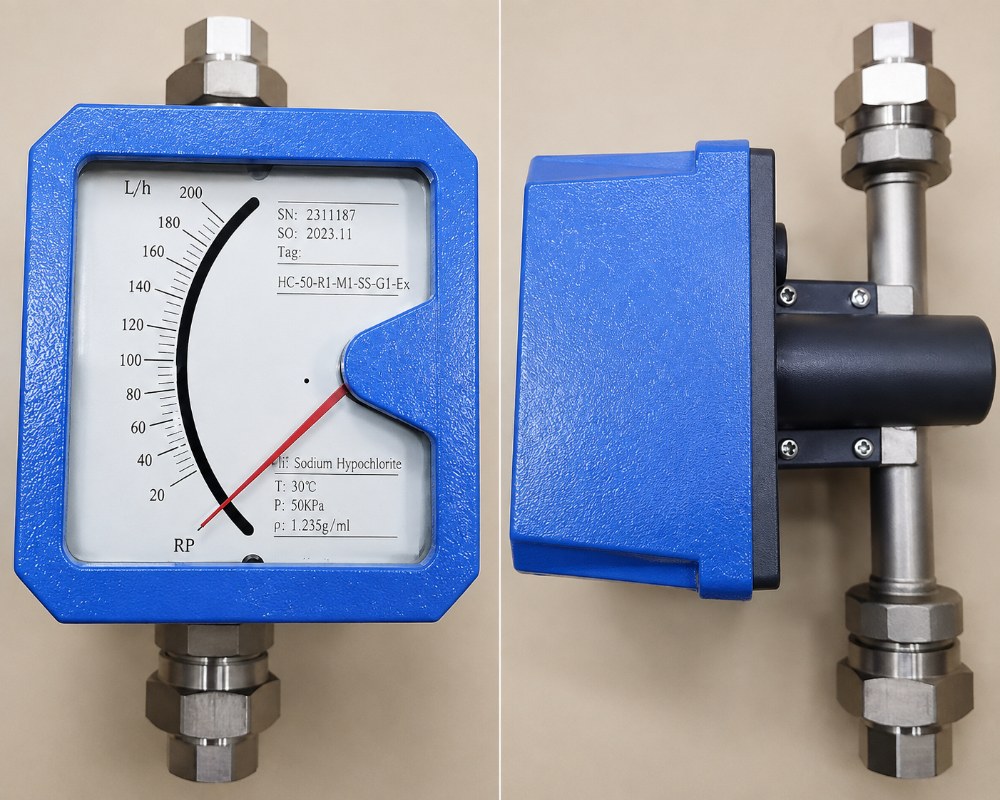
Screw connection rotameters
3) Flanged connection rotameters– The most common type, frequently used for instruments with diameters ranging from 15 to 100 mm.
Divided into three types: for liquids, for gases, and for steam.
In practice, most rotameters can be used for both liquids and gases, as they share a universal structural design. However, according to Chinese industry standards for rotameters (e.g., JB/T 6844-93), the maximum flow rate must comply with the series (1, 1.6, 2.5, 4, or 6) × 10ⁿL/h (where n is a positive/negative integer or zero). When a meter designed for liquids (typically water) is used for gases (typically air), it fails to meet this requirement. As a result, separate float and tapered tube designs are necessary for gases, leading to distinct liquid and gas series.
Some international manufacturers list flow rate ranges for both liquids and gases on the same meter, though the values are not always rounded figures. Certain domestic models also adopt this approach. Nevertheless, key design differences exist between liquid and gas meters—for example, gas meters use lighter floats and incorporate specialized damping mechanisms to prevent float oscillation (see Figures 2(a) and 2(b)).
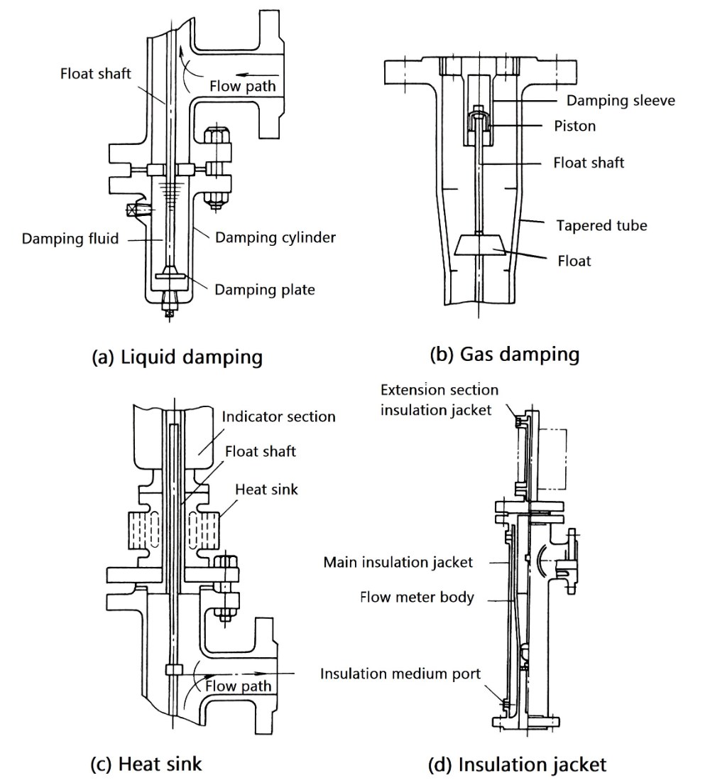
Figure 2: Schematic diagram of additional functional components
Steam measurement can only be performed using specially designed metal tube rotameters or by equipping standard models with additional components. For instance: adding liquid damping devices with heat sinks to minimize float pulsation; installing heat sinks at the connection between the indicating and converting sections (refer to Figure 2(c)).
Specialized Rotameter Designs for Challenging Applications
This refers to general-purpose instruments excluding special application models, and represents the most widely used configuration.
When a liquid in a pipeline with a temperature higher than the ambient flows through the meter, it may cool down due to increased heat dissipation surfaces, leading to solidification or crystallization that can cause poor float movement. Alternatively, a significant change in fluid viscosity due to temperature drop may affect measurement accuracy. In such cases, a jacketed insulation type (see Figure 2(d)) should be selected.
Sometimes, to prevent the fluid from absorbing external heat, the jacket is evacuated to achieve an insulating effect. In the past, glass tube rotameters with electric heating tubes or steam heating tubes for insulation were available abroad, but they are now rarely seen. Domestically, jacketed insulated metal tube rotameters are available, which can be heated and insulated by introducing steam or hot water.
When used in environments with explosive gases or dust, explosion-proof remote transmission rotameters must be selected. In China, two types of explosion-proof designs are available: explosion-proof enclosures and intrinsically safe circuits.
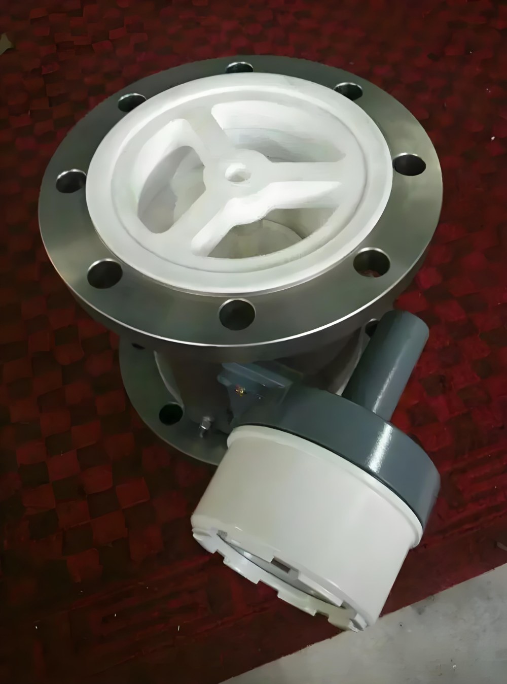
Teflon lined metal tube rotameter for corrosive fluids
Standard metal tube rotameters are constructed from acid-resistant steel.
Glass tube rotameters utilize acid-resistant steel or engineering plastics for wetted components along with a borosilicate glass metering tube, offering moderate corrosion resistance but with limited chemical compatibility.
China now produces specialized corrosion-resistant glass rotameters and corrosion-resistant metal tube rotameters for aggressive media applications.
The structural components in contact with the medium (such as the support frame) and the float are made of engineering plastic F4 (polytetrafluoroethylene, PTFE) or copolymer fluoroplastics such as F40 or F46, which are used as linings over metal parts (e.g., guide rods, sufficiently weighted floats, and the inner cavity of the base). Fluoroplastics exhibit excellent corrosion resistance—for example, PTFE (F4) is resistant to almost all media except for a few, such as liquid fluorine, liquid oxygen, and ozone.
While glass is highly corrosion-resistant to most media, it cannot be used with certain substances, including fluorine-containing media (e.g., hydrofluoric acid, calcium fluoride), hot and concentrated alkali solutions (e.g., sodium hydroxide).
In such cases, transparent engineering plastics must be used instead. For example:
Since these variants no longer use glass, they should not be referred to as "glass tube rotameters" but rather as "transparent conical tube rotameters."
Corrosion-Resistant Metal Tube Rotameters also adopt structural designs incorporating F4 (PTFE) components and F40/F46 fluoroplastic-lined metal parts. However, the accuracy of corrosion-resistant rotameters is generally lower than that of standard models.
In the semiconductor industry, where the measured fluid must not come into contact with metal ions (even if not for corrosion resistance), the entire flowmeter must be constructed from engineering plastics. Since glass contains trace metal ions, the conical tube must also be made of transparent engineering plastics.
Purge Flow Type Rotameters: Low Flow Rate Applications
The English name is "purge meter", also known as gas/liquid purge type or cleaning-type instrument. The typical structure is shown in Figure 3. It is a specialized instrument designed for low flow rates—20–3000 L/h for air and 0.3–100 L/h for water—with relatively low accuracy requirements, typically featuring a basic error of 2.5%–5% FS (sometimes as high as 10% FS).
The purge-type rotameter is often integrated with a small self-operated differential pressure regulator, enabling automatic flow stabilization despite fluctuations in the power source pressure or downstream parameter disturbances. Its working principle is illustrated in Figure 4.
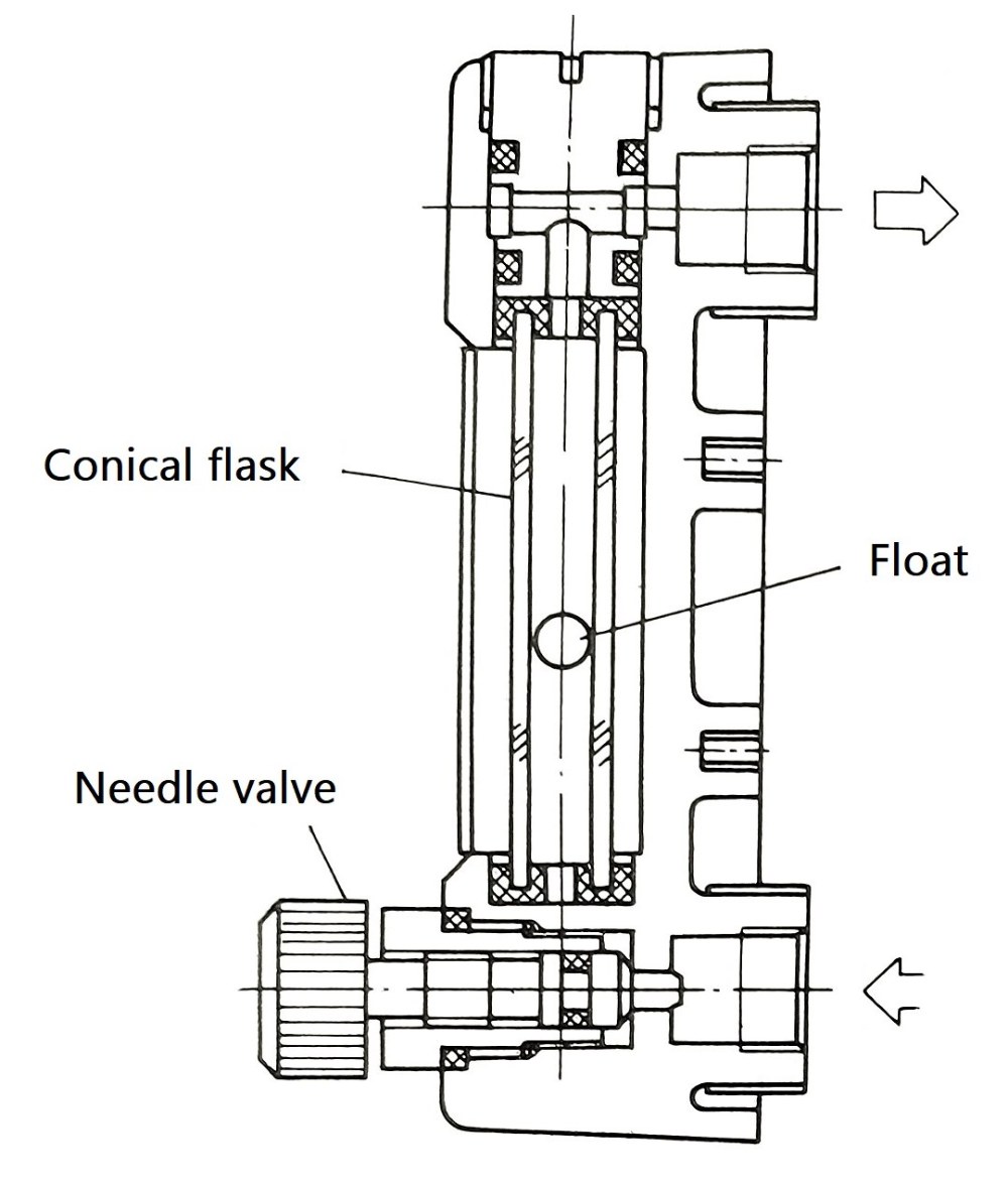
Figure 3: Purge flow type rotameter
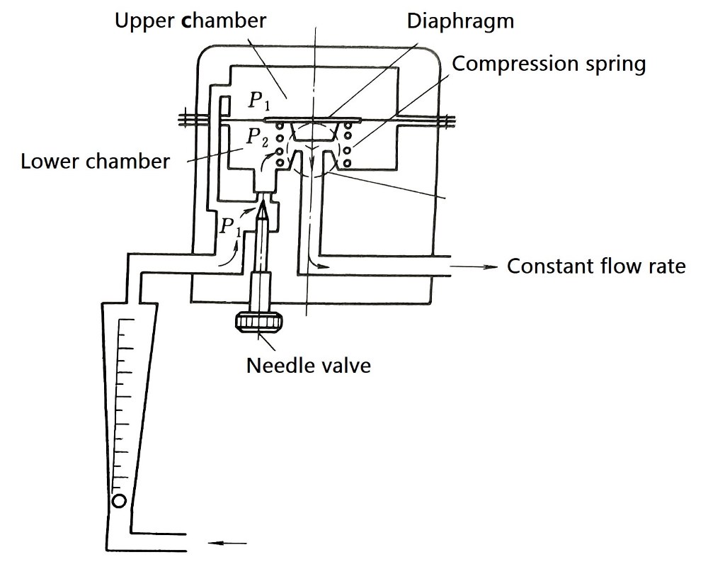
Figure 4: Rotameter flow regulator
When purge flow type used for measuring liquid level or density in containers, or for differential pressure-based flow measurement of dirty fluids in pipelines, the purge-type rotameter monitors or controls the purge gas (or liquid) flow into the vessel or differential pressure impulse lines.
The measurement principle and piping arrangement are illustrated in Figure 5. The purge gas is typically air or nitrogen, with a common flow rate of 60 L/h.
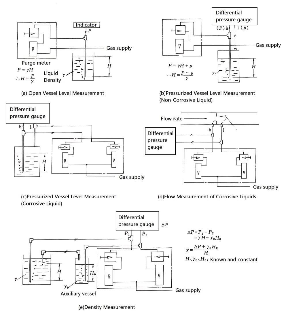
Figure 5: Application examples of purge flow type rotameter
Full-Flow vs. Bypass Rotameter Configurations
Classification types based on the flow rate of measured fluid through the rotameter
This type refers to flow meters where the entire measured fluid passes through the rotameter.
Bypass Rotameters: Cost-Effective Solutions for Large Pipe Applications
Unlike full-flow models, only a portion of the measured fluid passes through the float-based flow sensing element. The bypass rotameter consists of a standard orifice plate (or averaging pitot tube) installed in the main pipeline, combined with a small-bore rotameter. It is commonly used for larger pipe diameters (over 50mm), high-flow applications, and local indication where cost-effectiveness is critical.
Bypass rotameters are structurally classified into two types: separable type and integrated type.
The integrated-type meter combines the orifice plate and rotameter into a short pipe section, which is directly mounted onto the pipeline (see Figure 6 for schematic and working principle). It offers easy installation and is available in configurations for both horizontal and vertical pipelines, but must be positioned where the gauge reading is easily visible. The main pipeline typically has a diameter of 50–300 mm, with the orifice β ratio (d/D) ranging between 0.3–0.7, a differential pressure (ΔP) of 0.6–100 kPa, and a rotameter bore size of 10–25 mm.
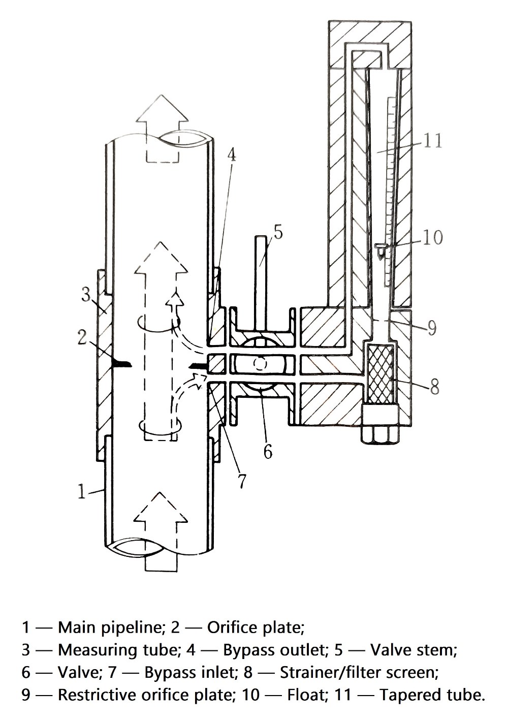
Figure 6: Working principle of bypass rotameter
The bypass rotameter allows for higher flow velocity selection compared to full-flow models, with liquid flows reaching 2.5–3 m/s and even up to 4–5 m/s.
Since the bypass line is equipped with a restrictive orifice plate, it compensates for the square-root nonlinearity between the orifice flow rate and differential pressure, resulting in a near-linear flow indication and a wide turndown ratio (typically 10:1). The accuracy ranges between 2.5%–4% FS.
An integrated bypass rotameter, known as the "Dual-Channel Auto-Switching Glass Tube Rotameter," features a concentric design where a transparent straight tube (outer channel) surrounds the tapered tube (inner channel) containing two floats of different densities.
At low flow rates, the outer flow channel remains closed by the instrument's internal valve, forcing all fluid through the inner tapered tube. The two floats (light and heavy) provide segmented low-flow measurement within the inner channel. When flow increases beyond a set threshold, the valve automatically opens, diverting partial flow to the outer channel. This flow division causes the floats to descend while maintaining measurable positions, effectively expanding the indicated flow value by several-fold. This unique dual-mode operation achieves an exceptional turndown ratio of 750:1.
This flowmeter is exclusively designed for use with clean liquids only, as particulate matter may compromise the switching mechanism's reliability.
How to Choose the Right Rotameter Type for Your Needs ?
When selecting a rotameter for your industrial application, consider these key factors based on the classifications outlined above:
Material Compatibility:
Signal Requirements:
Installation Constraints:
Application Environment:
Flow Range and Accuracy:
Choosing the optimal rotameter configuration requires careful consideration of your specific process conditions, accuracy requirements, and installation constraints. With multiple classification categories and specialized variants available, the selection process can be complex.
Our technical experts specialize in rotameter applications across diverse industrial environments and can help you:
✅ Analyze your process requirements and recommend the most suitable rotameter type
✅ Compare different classification options to optimize performance and cost-effectiveness
✅ Provide detailed specifications for material compatibility and accuracy requirements
✅ Offer installation guidance and technical support throughout your project
Contact our flow measurement specialists today for a free consultation and customized recommendation for your specific application.
Get Your Expert Consultation →