
English
Direct mass flow measurement.
High accuracy: 0.1 %~0.2%.
Also measure density, temperature, pressure.
For all fluids measurement.
Robust Gas flow meter for natural gas,LPG,biogas flow measurement.Inquiry Gas TUF Flowmeter price with EVC directly from China manufacture.
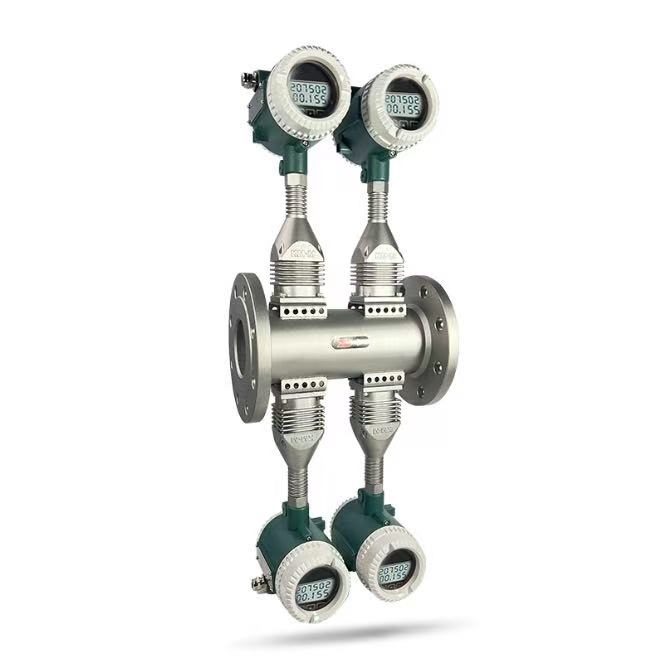
The new generation of isolated and seismic-resistant inductive vortex flowmeter is a world-leading milestone in the history of vortex flowmeters. The flowmeter housing adopts an integral structure, which is sturdy, without sealing parts, installation screws, or leaks, ensuring safety and reliability. It is equipped with isolation and allows for on-site sensor replacement without stopping the flow. The sensor has excellent seismic resistance, as well as high pressure and high temperature performance. The transmitter is equipped with advanced electronic signal spectrum scanning and processing circuits, further optimizing seismic resistance. It offers precise measurement, wide range, low minimum flow rate, safety, reliability, low operating costs, and minimal pressure loss. This product has a wide range of applications and has become a truly "universal flowmeter". The isolated and seismic-resistant inductive vortex flowmeter is sure to be favored by designers, specifiers, and a wide range of users.
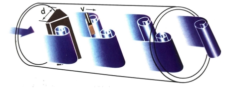
The inductive vortex flowmeter is a volumetric flowmeter that operates based on the principle of the Karman vortex street. Inside the flowmeter housing, there is a triangular prism called the bluff body. When the fluid flows past the bluff body, low-pressure zones are formed on both sides of the bluff body, creating regular vortices alternately on each side, known as Karman vortices. As shown in Figure 1.1, the vortices are asymmetrically arranged downstream of the bluff body. The flow velocity and volumetric flow rate of the vortex flowmeter are directly proportional to the frequency of the vortices. It is mainly used for measuring the flow of industrial pipeline fluids, such as gases and vapors. It has a small size, a wide range of measurement, high accuracy, and is almost unaffected by parameters such as fluid density, pressure, temperature, and viscosity when measuring volumetric flow rates. It has no moving mechanical parts, resulting in high reliability and low maintenance requirements. The instrument parameters can remain stable for a long time.
Given: Vortex frequency f, average fluid velocity V, bluff body width d, flowmeter inner diameter D, the relationship can be derived as follows:
- f = St * V / [(1-1.25*d/D)*d]
- Where:
- f: Vortex frequency
- V: Fluid flow velocity
- d: Width of the bluff body
- D: Inner diameter of the flowmeter
- St: Strouhal number
- Schematic diagram of the working principle of Karman vortex flow meter
|
Process fluids |
Liquids, Gas and Steam. |
|||||||
|
Saturated steam can be regarded as single-phase fluid when its dryness |
||||||||
|
Process |
Standard: -40~+250°C~350°C |
Extended:>+350°C~500°C |
||||||
|
Pressure rating |
Standard:≤2.5MPa~4.0Mpa |
Extended:>4.0MPa~45MPa |
||||||
|
Accuracy |
Liquid: |
±0.5% |
±1.0% |
±1.5% |
|
|||
|
Gas: |
±0.5% |
±1.0% |
±1.5% |
±2.5% |
||||
|
Turndown |
Standard:8:1~20:1 |
Extended:≥30:1 |
||||||
|
Reynolds number |
Standard:2x10⁴~7x10⁶ |
Extended:1x10⁴~7x10⁶ |
||||||
|
Flow velocity |
Liquid:0.21~7.6m/s Gas/steam standard velocity range:2~76m/s, extended <1.98m/s |
|||||||
|
Resistance factor |
Full pipe type:Cd ≤2.4 |
|||||||
|
Permitted max. vibration acceleration |
0.5g-1.5g |
|||||||
|
Straight pipe length |
Upstream straight pipe length ≥ 20D Downstream straight pipe length ≥ 5D |
|||||||
|
Pressure loss |
△P=1.29*ρ*V2 ρ:density (kg/m3),V:velocity(m/s) |
|||||||
|
Minimum upstream pressure (liquids) |
Pmin≥2.7*ΔP+1.3*P0 P0: liquid vapor pressure at operating conditions (Pa) |
|||||||
|
Protection rating |
Standard: IP65 |
Extended: IP68 |
||||||
|
Ex mark |
Intrinsically safe type: Ex ia IIC T1~T4 Ga |
|||||||
|
Ambient conditions |
Ambient temperature |
-40~+55°C non-explosion-protected areas |
||||||
|
-20~+55°C explosion-protected areas |
||||||||
|
Relative humidity |
non-condensing |
|||||||
|
Atmospheric pressure |
86~106kPa |
|||||||
|
Power supply |
Pulse: 12VDC~+24VDC Current:+24VDC 4-20mA Battery: 3.6V |
|||||||
|
Power |
<1w |
|||||||
|
Output signals |
Frequency/pulse output: 2~3,000Hz low level ≤1V high level ≥5V |
|||||||
|
2 wires, 4~20mA output: For exploration-protected type, load resistance ≤300Ω For non-exploration-protected type, load resistance ≤500Ω |
||||||||
|
Display |
Flow rate, volume flow, flow unit, flow percentage, etc. |
|||||||
|
Communication protocol |
HART、Modbus RTU(RS485) |
|||||||
|
Electrical Conduit |
M20*1.5 (F) |
|||||||
|
1/2”-14 NPT (F) |
||||||||
|
Body & bluff body |
Standard Material:304 SS |
|||||||
|
Mark |
|
|||||||
|
STLU |
Silver Automation Instruments Vortex Flow meter |
|||||||
|
Code |
Working Principle |
|||||||
|
G |
Isolated type Karman Vortices Flowmeter |
|||||||
|
Code |
Process Connection |
|||||||
|
1 |
Flanged(DN50~DN300) |
|||||||
|
2 |
Wafer type (DN15~DN300) |
|||||||
|
3 |
Fixed Inserted |
|||||||
|
4 |
Adjustable Inserted (without Ball Valve) |
|||||||
|
5 |
Adjustable Inserted (with Ball Valve) |
|||||||
|
6 |
Tri-clamp |
|||||||
|
7 |
Thread ( please specify thread standard) |
|||||||
|
Code |
Measured Fluid |
|||||||
|
2 |
Liquid |
|||||||
|
3 |
Gas |
|||||||
|
4 |
Steam |
|||||||
|
Code |
Nominal Diameter |
|||||||
|
015 |
15mm |
05 |
50mm |
15 |
150mm |
|||
|
020 |
20mm |
06 |
65mm |
20 |
200mm |
|||
|
02 |
25mm |
08 |
80mm |
25 |
250mm |
|||
|
03 |
32mm |
10 |
100mm |
30 |
300mm |
|||
|
04 |
40mm |
12 |
125mm |
Others |
Inserted ≥250mm |
|||
|
Code |
Indicator |
|||||||
|
D |
With Digital Indicator |
|||||||
|
N |
No Indicator ( 3 wire, pulse frequency output) |
|||||||
|
Code |
Power Supply |
|||||||
|
1 |
24V DC |
|||||||
|
2 |
3.6V Lithium Battery |
|||||||
|
Code |
Output Signal |
|||||||
|
0 |
No output |
|||||||
|
1 |
Pulse Output |
|||||||
|
2 |
Two Wire :4~20mA DC |
|||||||
|
4 |
Hart Protocol |
|||||||
|
5 |
RS-485 (Modbus) |
|||||||
|
Code |
Fluid Temperature |
|||||||
|
1 |
Standard -40~250°C |
|||||||
|
3 |
High Temperature Type :+100~+350°C |
|||||||
|
4 |
High Temperature Type :+350~+500°C |
|||||||
|
2 |
Specify |
|||||||
|
Code |
Pressure Rating |
|||||||
|
Code |
Standard |
Code |
Standard |
Code |
Standard |
|||
|
G0 |
GB 1.0Mpa |
D0 |
DIN PN10 |
A1 |
ANSI Class 150 |
|||
|
G1 |
GB 1.6Mpa |
D1 |
DIN PN16 |
A2 |
ANSI Class 300 |
|||
|
G2 |
GB 2.5 Mpa |
D2 |
DIN PN25 |
A3 |
ANSI Class 600 |
|||
|
G3 |
GB 4.0 Mpa |
D3 |
DIN PN40 |
S |
Special |
|||
|
Code |
Explosion Proof |
|||||||
|
N |
Non |
|||||||
|
d |
Flameproof |
|||||||
|
i |
Intrinsically Safe |
|||||||
|
Code |
Flow Meter Construction |
|||||||
|
0 |
Compact display |
|||||||
|
1 |
Remote display ,specify cable length |
|||||||
|
Code |
Protection Level |
|||||||
|
0 |
IP65 |
|||||||
|
1 |
IP67 |
|||||||
|
2 |
IP68 |
|||||||
|
Code |
Compensation |
|||||||
|
B0 |
Non compensation |
|||||||
|
BT |
Built-in temperature compensation |
|||||||
|
BP |
Built-in pressure compensation |
|||||||
|
BPT |
Built-in temperature and pressure compensation |
|||||||
|
EPT |
External temp & pressure compensation (RTD, pressure transmitter and flow totalizer) |
|||||||
|
EP |
External pressure compensation (pressure transmitter and flow totalizer) |
|||||||
|
ET |
External Temperature compensation (pressure transmitter and flow totalizer) |
|||||||
|
Code |
||||||||
we will contact you within 24 hours..