Max 48 channels universal inputs
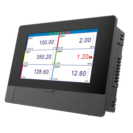
10.4 inch TFT color LCD display
In stock fast delivery
E-thernet or SD card options Not find what you need or not sure what you choose? Email us: sales@silverinstruments.com
Whatsapp: +86 18936759191
This article introduces the 48 channels paperless recorder fundamental principles, software and hardware architecture, as well as the design concepts and methods for certain key technical processes of a color paperless recorder. Finally, the main performance indicators of the 48 channels digital recorders are presented.
The 48 channels color paperless recorder is a new-generation recording instrument composed of a multi-microprocessor network, offering powerful functionality and excellent real-time performance.
48 channels paperless recorder key features:
Max 48 channels of universal input for standard voltage, current, thermocouple, and RTD signals, simplifying installation and calibration.
48 channels chartless recorder accept signal types
Advanced A/D conversion and self-calibration technologies, enhancing resistance to temperature drift and time drift, while effectively filtering out interference in harsh environments.
A combination of large-capacity RAM (1MB) with power-off protection and SD storage cards (128MB–1GB) to balance short-term data access and long-term data storage.
A 10.4-inch TFT true-color LCD screen, significantly expanding display capabilities.
User-friendly interface with multiple display modes, including engineering units, bar graphs, and trend curves for easy monitoring.
A flexible 5-level English menu for system configuration, with password protection for parameter settings.
RS-232/RS-485 communication interfaces, enabling PC data exchange, host computer configuration, and connection to mini serial printers for real-time data and alarm status printing.
A dedicated aluminum alloy casing for enhanced EMI resistance, easy installation, and an aesthetic, practical design.
Widely applications of color paperless recorders
48 channels panel logger is widely applicable in chemical, metallurgical, petroleum, and other industries, it enables sampling, monitoring, analysis, and storage of industrial process parameters. Compared to traditional mechanical chart recorders, graphical recorder eliminates issues such as paper jams, ink leakage, complex mechanical structures, high maintenance costs, and limited functionality, making 48 channels universal recorder an ideal next-generation instrument for industrial automation.
Paper Recorder
Working Principle of 48 channels data logger recorder
The channel board performs sampling and amplification on each analog input signal, then transmits it to the A/D conversion module.The signal is converted into a digital value by the A/D converter, processed through digital filtering, and stored in the data storage area.The channel board CPU communicates with the main board CPU every 0.2 seconds to transfer measurement data.The main board processes the data by converting it into engineering values or fitting curves (corresponding to display coordinates) and displays the information across different screens.The CPU stores measurement values in both:RAM (temporary real-time storage),Flash memory card (long-term data retention).The system performs high/low limit alarm checks and outputs alarm status via relay contacts based on alarm configuration settings.
The CPU receives keyboard operation commands via the data bus and performs corresponding processing and display based on these commands. All configuration parameters are stored in EEPROM. According to the print settings, the CPU transmits relevant data to the printer through the RS-232 communication interface for printing.
Hardware Structure of 48 channels data logger recorder
The 48 channels graphical recorder consists of six main components: the main board, channel board, display screen, keyboard, memory card, relay output board, communication board, and power supply. These components are interconnected via ribbon cables and bus slots. As figure 1 show.
1. Display Screen
The digital chart recorder with 48 channels inputs features a dot-matrix color LCD display with a resolution of 800×600 pixels, capable of displaying 128 colors. This enables the presentation of English characters, graphics, and tables.
48 channels Paperless recorder has multiple display modes
2. Main Board
Main board of 48 channels electronic recorders
The main board primarily comprises a microcontroller system and a signal switching unit.
Figure 1: Hardware Structure
2.1 System Microcontroller
The system employs 8-bit microcontrollers (80C32 and 80C31) to perform signal measurement, computation, screen display, alarm output, and communication functions. Important elements consist of: CPU,EPROM,RAM WDT (Watchdog Timer): the Real-Time Clock (RTC).
During unplanned power outages or shutdowns, the RAM with power-fail protection guards against the loss of internal settings and recorded data. For the panel digital recorder to function properly, important data and communication parameters must be protected.
System crashes brought on by outside interference are avoided by the WDT. The WDT ensures uninterrupted operation by resetting the CPU within a predetermined time frame in the event that interference causes the CPU or EPROM to malfunction.
The 48 channels chartless recorder's real-time timing is provided by the RTC. Internal timers are no longer necessary, and the CPU's resource consumption is greatly decreased, as it only needs to read the clock data on a periodic basis for display. In order to preserve real-time clock functionality and safeguard RAM data in the event of a power outage or shutdown, the RTC chip has an integrated lithium battery.
These parameters include calibration data, signal type, measurement range (upper/lower limits), engineering units, data logging intervals, and alarm thresholds. The chip's two-wire interface (I²C) minimizes system resource consumption.
2.2 Relay Control Unit
The relay control unit generates switching signals for the relays based on the alarm output status.
3. Channel Board
As 48 channels data logger accepts standard analog signals as well as thermocouple and RTD signals, the main unit must perform a series of signal processing functions:Microcontroller-controlled multiplexer switching, Millivolt signal amplification,A/D conversion,Storage of converted data (arithmetic mean) in designated microcontroller memory.
The microcontroller system periodically communicates with the channel board, sending commands and receiving sampled data while maintaining inter-channel isolation.
4. Power Supply Circuit
The 48 channels chartless recorder employs a low-voltage switching power supply for improved conversion efficiency and reduced power consumption. The circuit accepts either:220V AC, 50Hz;24V DC,to accommodate different industrial environments.please specify your demand for main power supply demand when you ordering 48 channels recorder from silverinstruments.com
5. Enclosure
Constructed with specialized aluminum alloy profiles, featuring a panel cutout dimension of 280 mm × 280mm.
48 channels digital recorder dimensions
Key Technologies of 48 channels universal recorder
1. Universal Signal Input:
The recorder implements universal signal input through:Rear terminal wiring,DIP switch settings,System menu configuration. Operating Principle (See Figure 2):
Figure 2: Principle of universal signal input
Switch states (S1/S2) configuration:Thermocouple signals: S2 open, S1 closed;Standard signals: S1 open, S2 closed;RTD signals: Both S1 and S2 open.
2. RTD Sampling
The instrument uses analog switches for channel selection during RTD sampling. To compensate for unknown and variable on-resistances in analog switches:Circuit Design Solution (See Figure 3):
Current source generates voltage across RTD/reference resistor
Voltage measurement at Y terminal eliminates switch resistance effects
Precision is maintained by measuring pre-switch voltage
Technical Specifications of 48 channels paperless recorder
Basic error: ±0.2%;
Historical playback error: ±0.1%;;
Alarm error: ±0.1%;
Repeatability error: 0.1%;
Alarm repeatability error: 0.1%;
Serial interface: RS-232;
Power supply: AC 220V ±15% or DC 24V.
In conclusion
the color paperless recorder with 48 universal channels inputs has excellent features including wide applicability, user-friendly display operation, high accuracy and reliable operation, and powerful functionality - far surpassing traditional paper recorders or ink recorders. The electronically recorder is ideally suited for process parameter measurement and recording across various industries such as petroleum, chemical, food processing, water supply, and wastewater treatment. With its amaizing performance and low price cost from silverinstruments.com, this advanced panel recorder is anticipated to become more and more important in automated production processes.
Welcome to silverinstruments.com to obtain 48 channels paperless recorders factory price.