SILVER AUTOMATION INSTRUMENTS LTD.
Product Category

By Media
Flow Meter

Gas Turbine Flow Meter Installation & Maintenance


Proper Installation of Gas Turbine Flow Meters

gas turbine flow meter

Gas turbine flow meter


Modern plants rely on accurate gas metering for natural gas, CO₂, LPG/SNG, hydrogen, nitrogen, oxygen, and compressed air. In these services, the gas turbine flow meter plays a vital role by delivering fast, repeatable measurement with low pressure loss. Its operating principle is simple and robust: the flowing gas drives a multi-blade rotor, the rotational speed is proportional to the average flow velocity, and a magnetic or optical pickup converts blade passage into pulses. With a calibrated K-factor (pulses per unit volume), the transmitter outputs totalized volume and a 4–20 mA or pulse signal for control and reporting.

Proper install of gas turbine flow meter to get best measurement result

Getting accurate results depends not only on choosing the right meter for the customer’s process, but also on correct installation. The following guide explains, step by step, how to install a gas turbine flow meter properly.


Scope & Safety

Installing a gas turbine meter correctly affects both measurement performance and pipeline safety. Only qualified technicians with piping and hazardous-area competence should perform the work. Follow local codes and site procedures, and never open flanges or housings while the line is pressurized. In Ex areas, preserve explosion-proof integrity—use certified glands and never modify cable entries or sealing methods.

Core safety rules:

  • Do not attempt repairs or dismantling under pressure.
  • Do not break calibration or lead seals without authorization.
  • Lock-out/tag-out (LOTO) before maintenance.
  • Keep the bypass valve locked during normal operation.

Pre-Installation Checklist

A turbine meter needs a clean, stable flow profile. Before you bolt anything up:

  • Clean the pipeline: Remove welding slag, rust, dust, and debris. Fouling is the #1 cause of early bearing wear and accuracy drift. Add an upstream filter/strainer where debris is likely.
  • Avoid pulsation: Don’t install where pulsating flow or severe pressure oscillations are present. If unavoidable, add dampeners or relocate the meter to a calmer section.
  • Plan for stress relief: Use expansion joints/bellows so thermal growth and misalignment don’t bend the body. Check that the upstream/downstream spools are aligned and stress-free.
  • Choose the location: Stay away from strong magnetic fields, mechanical vibration, and high-EMI zones (near VFDs or high-power busbars).

Mechanical Installation & Piping Layout

Orientation & direction. Gas turbine meters are typically installed horizontally with the flow arrow matching the gas direction. Keep the body level and free from piping strain.

Straight runs (velocity profile). Provide at least 10 DN upstream and 5 DN downstream of straight pipe. If you have elbows in plane, reducers, control valves, or tees just upstream, extend upstream straight run to 15–20 DN, or add a flow conditioner to restore a symmetric profile. Keep gaskets flush with the bore—no gasket overhangs or intrusion from welds into the metering tube.

Coaxial alignment. Align flanges coaxially at the inlet and outlet. Misalignment creates swirl and uneven velocity, accelerating bearing wear and adding measurement error.

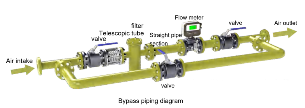
Bypass loop. Install a bypass line with isolation valves around the meter so you can service the instrument without shutting the plant. During normal operation, lock the bypass closed.


Commissioning & Startup

Pressurization ramp rate. Open the upstream valve slowly and increase pressure gradually. The maximum pressure-rise rate should not exceed 35 kPa per second. Rapid pressurization can overspeed the rotor and damage bearings.

Leak check & rotation. After pressurization, check for leaks at all joints. Verify the rotor turns freely (via diagnostics or pulse frequency at low flow) without vibration or noise.

Flow stabilization. Bring the line up to normal pressure and temperature before final zeroing or verification. If the process frequently runs near the minimum flow, consider a smaller meter or a multi-path solution to maintain linearity and repeatability.


Electrical Wiring & EMI Control

Cable type. Use twisted-pair shielded cable for 4–20 mA/HART or pulse outputs. Keep signal cables in a separate conduit from power lines. If a conduit entry can’t be sealed, orient it downward to prevent condensation.

Shielding & grounding. Ground the cable shield at one end only (typically the control room) to avoid loops. Ground the meter per the manufacturer—do not share instrument ground with high-voltage systems. During pipeline welding, never use the meter as a welding return.

Ingress protection. Seal unused entries with approved plugs. Add a drip loop in humid environments to prevent moisture from wicking into the terminal box.


Daily Maintenance & Condition Monitoring

Routine checks prolong meter life and preserve accuracy:

  • Process conditions: Periodically verify gas cleanliness, pressure, and temperature. Significant changes can shift calibration.
  • Filter health: Inspect upstream filters and replace or clean elements promptly to protect the rotor and bearings.
  • Environmental review: Watch for new EMI sources, added vibration, or moisture ingress that could cause signal drift.
  • Seal integrity: Keep calibration/lead seals intact unless approved work is in progress.

Lubrication of Gas Turbine Flow Meters

Turbine bearings need timely and effective lubrication. Proper lube improves wear and corrosion resistance and flushes fine particles, preserving linear accuracy and repeatability.

  • Under normal duty, lubricate 10–15 times per year, filling the oil cup to the marked level each time with the specified lubricant.
  • Prefer to lubricate while the meter is operating. After each handle stroke on the oiler, pause a few seconds before the next, until the specified volume is reached.
  • Do not lubricate when the meter is stopped or operating for long periods below 0.2 Qmax.
  • Increase frequency for high flow, high pressure, long-duty cycles, or dirty gas.
  • If the lubricant is contaminated or degraded, replace it and clean the oil cup before refilling.
  • Below is a video to show to you how to do lubricate oil procedure.

Recommended Lubrication Amounts (Reference Table)

Nominal Diameter (DN)

25

50

80

100

150

200

250

300

350

400

First-time / daily refueling (mL)

10 / 5

10 / 5

10 / 5

10 / 5

10 / 5

15 / 10

15 / 10

15 / 10

15 / 10

15 / 10


Troubleshooting Quick Guide

  • Unstable reading → Air entrainment, liquid slugs (wet gas), poor shielding/grounding, EMI, vibration.
    Fix: Dry the gas where possible, re-route cables, verify shield termination, add supports/dampers.
  • Zero shift or bias → Mechanical stress from piping, misalignment, or gasket intrusion; rotor drag from contamination.
    Fix: Re-align spools, verify gasket flush with bore, clean/inspect rotor and bearings.
  • Slow response → Oversized meter at very low velocities or sticky bearings.
    Fix: Re-evaluate meter size vs. turndown; verify lubrication and bearing condition.
  • Signal drift/moisture → Condensation in terminal box or conduit.
    Fix: Seal entries, add drip loops, dry terminals, use desiccant where appropriate.

When to Choose a Different Technology

Turbine meters excel on clean, dry gases with good Reynolds numbers and offer pulse outputs for totalization and custody transfer. For other scenarios:

  • Coriolis mass flow meter: Best for high pressure gas and when mass flow and high density gas are required; tolerant of composition changes and pulsation.
  • Ultrasonic gas flow meter: Ideal for large diameters, low pressure drop, and bi-directional metering; great where long straight runs are difficult (with conditioning).
  • Thermal mass flow meter: Useful for compressed air and utility gas monitoring when direct mass flow and wide turndown are priorities,suitable for low pressure gas measurement.

FAQs

Q1: What straight-run lengths are required for gas turbine flow meters?
A: Provide ≥10 DN upstream and ≥5 DN downstream of straight pipe. If elbows, tees, or control valves are immediately upstream, extend to 15–20 DN or install a flow conditioner.

Q2: How fast can I ramp pressure during startup?
A: Keep the pressure-rise rate ≤ 35 kPa/s to prevent rotor overspeed and bearing damage.

Q3: Do turbine meters work with pulsating flow?
A: Not recommended. Use dampeners, relocate to a stable section, or consider Coriolis for pulsating lines.

Q4: How often should I lubricate a gas turbine flow meter? And how to lubricate it ?
A: Typically 10–15 times per year, with volumes per DN size (see table). Increase frequency for high-pressure, high-flow, or dirty service.

Q5: What wiring practices prevent noisy signals?
A: Use twisted-pair shielded cable, ground the shield at one end only, keep signal cables away from power/VFD lines, and seal conduits to avoid condensation.


Conclusion

Following these gas turbine flow meter practices—clean piping, correct straight runs, stress-free mounting, controlled startup, robust EMI/grounding, and disciplined lubrication—delivers stable accuracy, longer bearing life, and safer pipeline operation. Where process conditions challenge turbine technology (pulsation, very low velocity, composition shifts), evaluate Coriolis, ultrasonic, or thermal mass alternatives.

Author: Silver Automation Instruments — Engineering Team

Practical instrumentation specialists with 10+ years of field experience in flow, pressure, and level measurement. Expertise in gas turbine, Coriolis, magnetic, and ultrasonic meters. CE & ISO 9001 processes.

Website: |  Email: technician@silverinstruments.com

  • Gas Turbine Flow Meter with Temp & Press. compensationGas Turbine Flow Meter with Temp & Press. compensation2018/08/27SGW-D series Gas turbine flow meter can be used to measure clean air or gas, such as natural gas, nitrogen gas.,etc. The best part of SGW series is that it can have integral temperature and pressure c...VIEW
  • Vortex type gas flow meterVortex type gas flow meter2022/06/04Overview of Vortex type gas flow meter Vortex flowmeter is a fluid oscillating flow measuring instrument developed according to the principle of "Kaman vortex street". The so-called "Kamen vortex stre...VIEW
  • Gas mass flow meterGas mass flow meter2020/01/31Coriolis princinple.
    Good for high pressure or high density gas.
    Direct mass flow measurement.
    For LPG, natural gas, H2,O2,Ar,Cl ....
    VIEW
  • Thermal Mass Flow MeterThermal Mass Flow Meter2017/05/27Low cost gas flow meter.
    No need temp & press compensation.
    Max for DN2000 diameter sensor size.
    No moving parts and low maintenance.
    VIEW
  • Low flow gas Flow Meter/Mass Flow ControllerLow flow gas Flow Meter/Mass Flow Controller2023/07/10For gas ultra low rate as low as 2 sccm (2 ml/min), For air,biogas,natural gas, N2, O2,CO2,etc. 1%F.S accuracy and 2s response time.VIEW
  • In-line large size gas turbine flow meterIn-line large size gas turbine flow meter2019/07/30DN350 (14 inches) \DN400 (16 inches) large size gas turbine flow meters can measure the flow of gas or air in closed pipeline. It can measure low pressure or high pressure gas. It is widely used for t...VIEW
Email
WhatsApp
Inquiry