
English
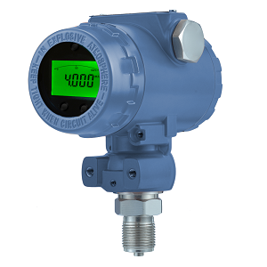
Installing a pressure
transmitter correctly is critical to ensure reliable, stable, and accurate
pressure, differential pressure, or liquid level measurements in any industrial
process.
This detailed guide from Silver Automation Instruments provides
step-by-step instructions and best practices for electrical installation, mechanical mounting, impulse line layout, and remote diaphragm
seal configuration.
Whether you are setting up a differential pressure transmitter, gauge
pressure transmitter, or level transmitter, proper installation guarantees
measurement precision, device longevity, and safe operation under demanding
industrial conditions.


Electrical wiring is the foundation for stable signal transmission. The power supply wire and signal wire share the same cable, simplifying installation and reducing potential wiring errors.
To begin, remove the housing cover on the terminal compartment side and connect the positive and negative leads to the corresponding terminals. Silver Automation Instruments recommends using a twisted-pair or shielded cable to minimize electromagnetic interference (EMI) and ensure signal stability, especially in environments with heavy electrical noise such as refineries, chemical plants, or power generation facilities.
If the conduit cannot be sealed, it should face downward (“adown”) to prevent condensation buildup inside the transmitter enclosure.
Proper electrical installation ensures that your pressure transmitter output (4–20mA, pulse, or digital HART/Modbus signal) remains stable and accurate throughout the operating life of the device.


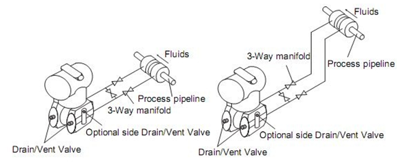
Pressure transmitters can be mounted directly on process taps or remotely using brackets and impulse lines. Silver Automation Instruments offers several mounting configurations, including:

These configurations allow flexible installation depending on plant layout and accessibility.
The process connection of most
transmitters is ¼ NPT on the flange, with adaptors available for ½
NPT taper threads.
When connecting impulse lines, tighten bolts incrementally in a cross
pattern to avoid distortion, using a maximum torque of 40 N·m.
Key mechanical recommendations:
Proper mounting of the pressure transmitter and impulse lines directly affects measurement accuracy and repeatability.
Impulse lines transfer pressure from the process taps to the transmitter. Incorrect impulse line design or installation can cause measurement drift or systematic errors.
These guidelines are essential for reliable differential pressure measurement and long-term transmitter stability.
In applications involving high viscosity, high temperature, or corrosive media, remote diaphragm seal transmitters are used to isolate the sensing element from the process fluid.
Best Installation Practices

Correct capillary routing and equal seal lengths ensure stable readings and accurate pressure or level measurement in reactors, tanks, and pipelines.
Different media require specific installation orientations to ensure accuracy and prevent trapped phases.
Liquid Flow Measurement
These guidelines guarantee accurate flow readings across different media and operating conditions.
Pressure transmitters can also be used to measure liquid level in open or closed vessels by detecting the hydrostatic pressure of the liquid column.
Connect the transmitter’s high-pressure
side to the bottom tap, with the low-pressure side vented to the
atmosphere.
If the transmitter and tap are on the same level:
![]()
Transmitter with the same level as tap
Px=x×ρ×g
where x = liquid height (m), ρ = fluid density (kg/m³), g = 9.80665 m/s².
Example: For x = 6.5 m and ρ = 1000 kg/m³,
Range = 0 ~ 63.7 kPa.
If the transmitter is higher or lower than the tap, additional terms (±hρ₀g) must be included to correct for height differences and fill fluid density (ρ₀).
![]()
Transmitter with higer level than Tap
![]()
Transmitter with lower level than Tap
In closed tanks, the
transmitter must compensate for vapor or gas pressure above the liquid.
Two main methods are used:
Example calculation (wet leg):
Range=g(yρ−hρ0) g[(x+y)ρ−hρ0]
This ensures the differential pressure reflects only the actual liquid level, not vessel pressure variations.
⚠️ Attention: The process medium should not freeze, or it may damage the isolation diaphragm or transmitter module.

Following these safety and environmental recommendations ensures long-term reliability and compliance with industrial standards.
|
Problem |
Likely Cause |
Recommended Solution |
|
Unstable reading |
Gas in liquid line / poor grounding |
Vent trapped air, check shielding |
|
Zero shift |
Horizontal capsule position |
Rotate housing, perform zero trim |
|
Slow response |
Long or unequal capillaries |
Shorten and equalize lines |
|
Drifting signal |
Moisture ingress |
Seal conduits and dry connections |
|
Incorrect level reading |
Temperature difference in legs |
Use equal-length impulse lines |
Proper preventive maintenance and installation checks can eliminate most issues encountered during field commissioning.
Silver Automation Instruments is a trusted pressure transmitter manufacturer in China, serving global customers across industries such as oil & gas, power generation, water treatment, and chemical processing.
We provide:
Visit our website www.silverinstruments.com to explore our full range of industrial automation instruments, including Coriolis mass flow meters, magnetic flow meters, and positive displacement flow meters.
Proper pressure transmitter
installation and wiring is vital for obtaining accurate process data and
maintaining plant efficiency.
By following the electrical, mechanical, and calibration recommendations
provided by Silver Automation Instruments, you can ensure your
transmitter performs reliably under all conditions — whether measuring steam
flow, tank level, or process pressure.
With careful attention to details like impulse line routing, capillary placement, and environmental protection, your transmitter will deliver years of precise, maintenance-free service.
 Ceramic Pressure Sensor
Ceramic capacitive pressure sensor. Flush and abrasion-resistant sensor. Pressure sensor output 4-20mA . For pulp and paper industry.
VIEW
Ceramic Pressure Sensor
Ceramic capacitive pressure sensor. Flush and abrasion-resistant sensor. Pressure sensor output 4-20mA . For pulp and paper industry.
VIEW
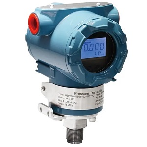 Pressure transmitter
Signal Crystal Silicon Resonant Sensor. High accuracy: 0.075%, 0.1%. Absolute pressure and gauge pressure.
VIEW
Pressure transmitter
Signal Crystal Silicon Resonant Sensor. High accuracy: 0.075%, 0.1%. Absolute pressure and gauge pressure.
VIEW
 Remote seal pressure transmitter
You probably looked for this articlebecause there is so much you need to understand about a remote seal pressuretransmitter in detail, which is, in some instances, referred to as a chemical ora diaphr...
VIEW
Remote seal pressure transmitter
You probably looked for this articlebecause there is so much you need to understand about a remote seal pressuretransmitter in detail, which is, in some instances, referred to as a chemical ora diaphr...
VIEW
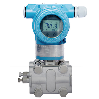 Differential Pressure Transmitters
Monocrystalline silicion sensor; Differential pressure transducers; High accuracy: 0.075%, 0.1%; Range: 0-5800 PSI; Ingress Protection: IP67;
VIEW
Differential Pressure Transmitters
Monocrystalline silicion sensor; Differential pressure transducers; High accuracy: 0.075%, 0.1%; Range: 0-5800 PSI; Ingress Protection: IP67;
VIEW
 SH 308 Series Pressure Transmitter
Piezoresistive pressure cost is low; High pressure transducer max 10000 PSI; ATEX approved
VIEW
SH 308 Series Pressure Transmitter
Piezoresistive pressure cost is low; High pressure transducer max 10000 PSI; ATEX approved
VIEW
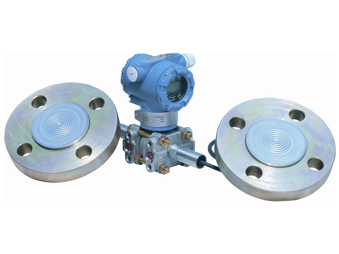
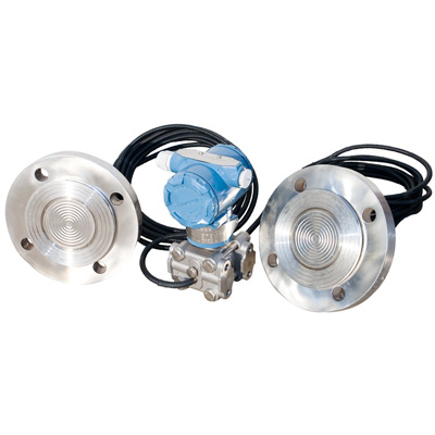 Pressure Transmitter with Remote Diaphragm seals
Remote diaphragm for corrosive or viscous fluids. DP Transmitters or Pressure Transmitters. 316L,HC, Tan, Monel diaphragm.
VIEW
Pressure Transmitter with Remote Diaphragm seals
Remote diaphragm for corrosive or viscous fluids. DP Transmitters or Pressure Transmitters. 316L,HC, Tan, Monel diaphragm.
VIEW