
English
Capacitive differential pressure transmitters are essential devices in modern industrial instrumentation and process automation. They use advanced capacitive sensing technology to measure differential, gauge, and absolute pressure with high precision and long-term stability. Unlike traditional mechanical pressure sensors, these transmitters have no moving mechanical transmission mechanisms, making them compact, durable, and highly resistant to vibration. The independent zero and span adjustments ensure accuracy without mutual interference, contributing to their widespread use across industries.

In China, Many cities have introduced manufacturing lines from the American company Rosemount, producing various models for differential pressure, gauge pressure, and absolute pressure measurement. Some units also include square root extraction for flow measurement, along with versions designed for high static pressure and micro differential pressure applications.
A capacitive differential pressure transmitter typically consists of two main units: a measurement section and a conversion/amplification section, as shown in Figure 1.

Figure 1: Capacitive Differential Pressure Transmitter Circuit Diagram
1—Oscillator 2—Capacitive
sensor 3—Demodulator 4—Range adjustment 5—Current limiter
6—Power amplifier 7—Operational amplifier 8—Zero adjustment and zero migration
9—Oscillation control amplifier 10—Reference voltage source 11—Voltage regulator
12—Polarity reversal protection
The capacitive sensor converts
the measured differential pressure (ΔP) into a change in capacitance. The high
and low differential capacitors, CH and CL, are excited by a high-frequency
oscillator. The resulting current variations are demodulated to produce
differential signals (iL − iH) and
common-mode signals (iL + iH).
The differential signal is compared to the feedback signal (If), then
amplified and converted into a DC 4-20mA output. This output current
flows through the load resistance and feedback network, maintaining a linear
relationship between the differential signal and the output current.
The capacitive sensor consists of a fixed electrode plate and a movable measuring diaphragm, forming two capacitors (CH and CL) connected to the high-pressure and low-pressure chambers. When differential pressure is applied, the diaphragm deflects, changing the capacitances. The high-frequency oscillator (typically 32 kHz) converts these capacitance changes into current variations, which are amplified and rectified to generate a 4-20 mA DC signal proportional to the applied differential pressure ΔP.
When the transmitter is used for flow measurement—such as with orifice plates, venturi tubes, or nozzles—the signal is passed through a square root extractor to obtain a linear relationship with flow rate. The device operates on a 24 V DC two-wire system, supporting supply voltages from 12–45 V DC and load resistances up to 600 Ω.
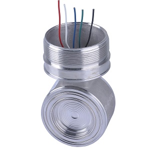
The two-chamber capacitive differential pressure sensor is shown in Figure 2.

Figure 2: The two-chamber structure of the capacitive differential pressure sensor
1, 4—Wave-patterned isolation diaphragm; 2, 3—Stainless steel base; 5—Glass layer; 6—Metal film; 7—Measuring diaphragm
In this structure, the metal films (6) act as fixed electrodes, while the measuring diaphragm (7) serves as the moving electrode. Both sides of the diaphragm form two separate chambers filled with silicone oil. The incompressible fluid transmits the differential pressure Δp = p_H − p_L to the diaphragm surfaces.
When Δp = 0, the capacitances
on both sides (CH and CL) are equal. When Δp ≠ 0, the diaphragm
deflects toward the low-pressure side, making CL > CH.
Using differential capacitance reduces errors caused by temperature
variations in the dielectric constant, thereby improving sensitivity,
accuracy, and linearity—important factors in industrial process control and pressure measurement.
When Δp ≠ 0, the capacitance variation is illustrated in Figure 3.

Figure 3: Capacitance Changes on Both Sides When Differential Pressure Exists
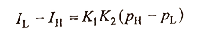
Equations:
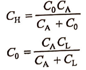
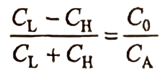
For a diaphragm with initial
tension, deflection is proportional to the differential pressure:
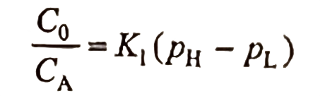
Here, K₁ is a structural constant depending on the diaphragm curvature, electrode spacing, and mechanical tension. This relationship ensures that the output current is directly proportional to the applied differential pressure, providing excellent measurement accuracy.
The capacitive pressure sensor converts differential pressure into a proportional capacitance change. Measuring this capacitance requires high-frequency AC excitation, typically around 32 kHz.

Figure 4: Oscillator Circuit Figure 5: Oscillator Power Supply
Oscillator Circuit (Figure 4)
The circuit comprises windings (terminals 6, 8 and 5, 7) and capacitor C₂₀ forming a resonant loop connected to a transistor VT₁. Bias resistor R₂₉ defines the static operating point. The frequency is determined by the inductance L and capacitance C.
Oscillator Power Supply (Figure 5)
Since capacitance measurement relies on AC voltage, the oscillator voltage must remain stable. A negative feedback control loop automatically stabilizes the voltage while ensuring sufficient starting amplitude.
As shown in Figure 6, the capacitive current generation circuit and voltage formation network maintain constant excitation.

Figure 6: Capacitive Current Generation Circuit and Voltage U₂ Formation Circuit
When Δp ≠ 0, C_H decreases and C_L increases, and the total current through both is expressed as:
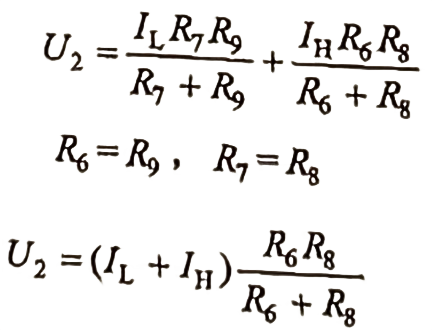
Automatic feedback ensures that IL + IH = K₂ (a constant), maintaining voltage stability and consistent sensitivity.
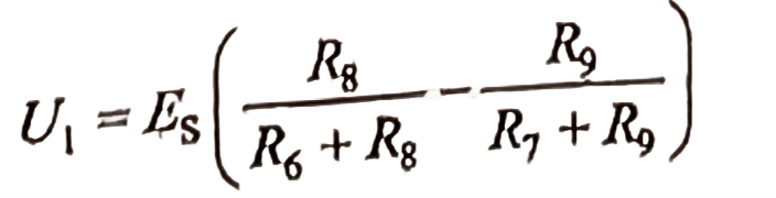
In the capacitive current
generation circuit:
![]()
![]()
![]()
Substituting earlier
relationships:
Total output current:
![]()
Thus, the 4-20 mA output
signal of the capacitive differential pressure transmitter is directly
proportional to the applied differential pressure.
The device also provides zero adjustment, range calibration, and reverse
polarity protection, ensuring stable and safe operation in industrial
pressure measurement systems.

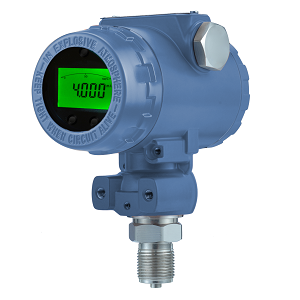
The SH Series pressure transmitters produced by silverinstrumens.com are widely used two-wire 4-20 mA pressure transmitters, designed for intrinsically safe and explosion-proof environments.
Key Specifications

Figure 7: Relationship between Power Supply Voltage and Load Resistance
When the supply voltage fluctuates by ±1 V, the output current variation remains below 0.005 %, ensuring signal stability and high accuracy.
The overall circuit of the SHGP/SHDP differential pressure transmitter is shown in Figure 8

Figure 8: Circuit Design of the SH series Model Capacitive Pressure Transmitter/DP
Key Components and Functions:
These elements ensure precise and stable performance across varying industrial conditions, making the SHGP/SHDP Series one of the most reliable capacitive differential pressure transmitters for process control and instrumentation worldwide.
 Low Pressure Transmitters
2025/10/12
Low pressure transmitter :16-60 mbar . High accuracy: ±0.1~0.5% Hart Protocol, 4-20mA ouput. Digital display mbar,psi,pa.
VIEW
Low Pressure Transmitters
2025/10/12
Low pressure transmitter :16-60 mbar . High accuracy: ±0.1~0.5% Hart Protocol, 4-20mA ouput. Digital display mbar,psi,pa.
VIEW
 Ceramic Pressure Sensor
2025/10/12
Ceramic capacitive pressure sensor. Flush and abrasion-resistant sensor. Pressure sensor output 4-20mA . For pulp and paper industry.
VIEW
Ceramic Pressure Sensor
2025/10/12
Ceramic capacitive pressure sensor. Flush and abrasion-resistant sensor. Pressure sensor output 4-20mA . For pulp and paper industry.
VIEW
 Capacitive pressure sensor 3351
2025/10/12
Capacitive pressure sensor or differential pressure sensor 3351; Accuracy: ± 0.1%; 0-40Mpa;
VIEW
Capacitive pressure sensor 3351
2025/10/12
Capacitive pressure sensor or differential pressure sensor 3351; Accuracy: ± 0.1%; 0-40Mpa;
VIEW
 SH 308 Series Pressure Transmitter
2025/10/12
Piezoresistive pressure cost is low; High pressure transducer max 10000 PSI; ATEX approved
VIEW
SH 308 Series Pressure Transmitter
2025/10/12
Piezoresistive pressure cost is low; High pressure transducer max 10000 PSI; ATEX approved
VIEW
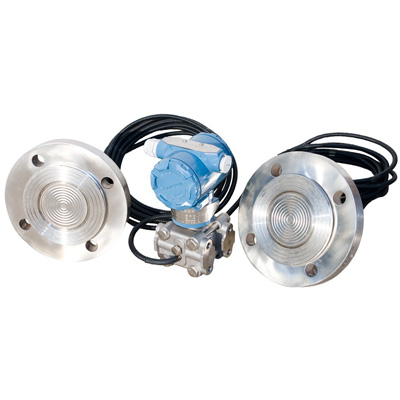 Pressure Transmitter with Remote Diaphragm seals
2025/10/12
Remote diaphragm for corrosive or viscous fluids. DP Transmitters or Pressure Transmitters. 316L,HC, Tan, Monel diaphragm.
VIEW
Pressure Transmitter with Remote Diaphragm seals
2025/10/12
Remote diaphragm for corrosive or viscous fluids. DP Transmitters or Pressure Transmitters. 316L,HC, Tan, Monel diaphragm.
VIEW
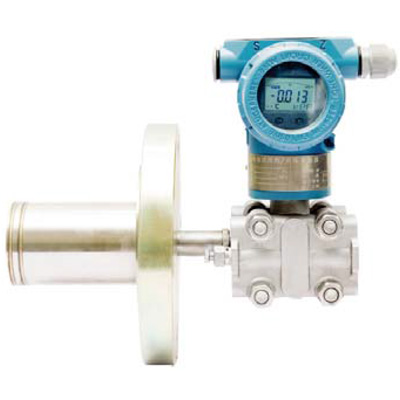 Pressure and DP Transmitter with Flange Diaphragm
2025/10/12
Flange diaphragm Transmitter. For pressure , level or DP; Digital transmitters with LCD display; HART, 4-20mA or MOUBUS;
VIEW
Pressure and DP Transmitter with Flange Diaphragm
2025/10/12
Flange diaphragm Transmitter. For pressure , level or DP; Digital transmitters with LCD display; HART, 4-20mA or MOUBUS;
VIEW