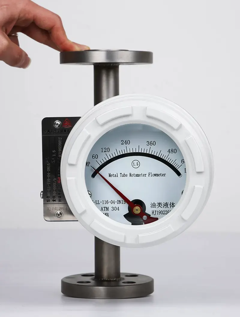
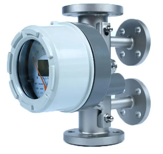
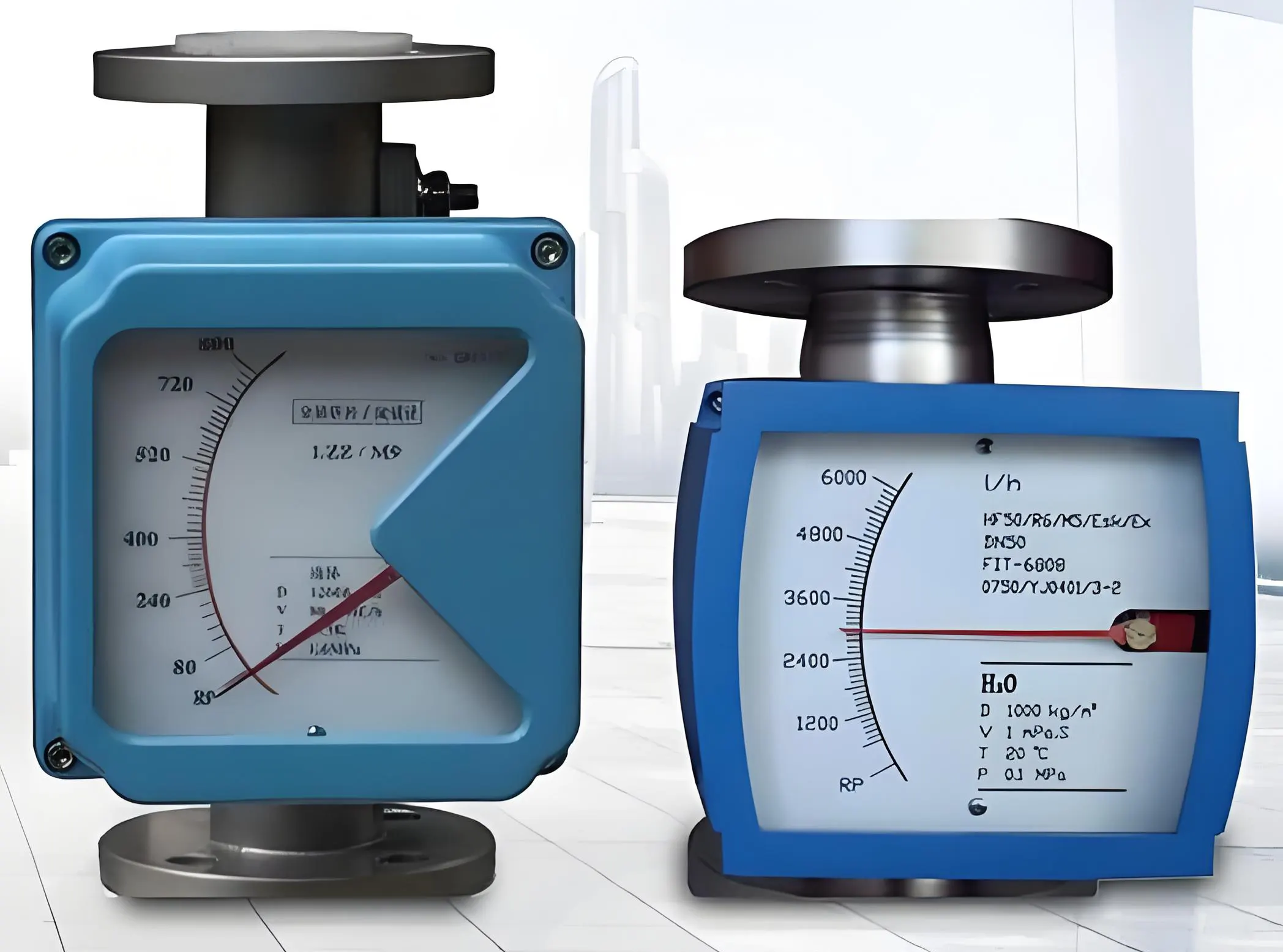
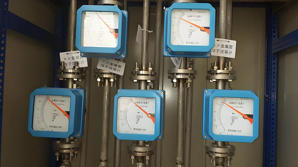
Variable area flow meter/rotameter
1. Introduction to Variable Area Flow Measurement
Variable Area Flow Meters (VA flow meters), commonly known as rotameters or float flow meters, are among the most widely used flow measurement devices in industrial applications; also this type flow meter has very long history. These local indication flow meters (now currently also has option with 4-20mA output) provide reliable, cost-effective solutions for measuring liquid , steam and gas flow rates in numerous process industries.
2. How VA flow meter( Rotameter) work ?
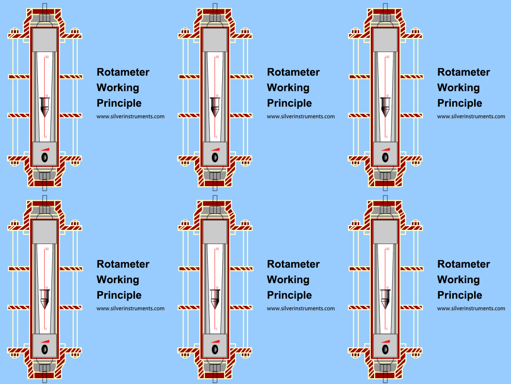
How variable area flow meter work
Rotameters operate on the variable area principle, where a float rises within a tapered tube in proportion to the flow rate. The annular area between the float and tube wall increases as the float moves upward, creating a balance between:
-
Buoyancy forces
-
Fluid drag forces
-
Float weight
This simple yet effective mechanism makes rotameters ideal for local flow indication where moderate accuracy (typically 1-5% FS) is sufficient.
3. Where are Variable area flow meter used?
As a visual flow indicator or for applications requiring moderate measurement accuracy, rotameters serve as local indicating instruments in over 90% of use cases. Float flow meters are widely adopted across process industries.
Process Industries
Oil & gas: Monitoring purge flows, chemical injection
Chemical processing: Acid/alkali flow measurement
Pharmaceuticals: Bioreactor feed control
Power generation: Cooling water flow monitoring
Utility Systems
Water treatment plants: Chemical dosing control
HVAC systems: Chilled water flow measurement
Compressed air systems: Leak detection
Specialty Applications
Environmental monitoring: Stack gas sampling (CEMS)
Laboratory equipment: Precise liquid dosing
Food & beverage: Sanitary process flow measurement
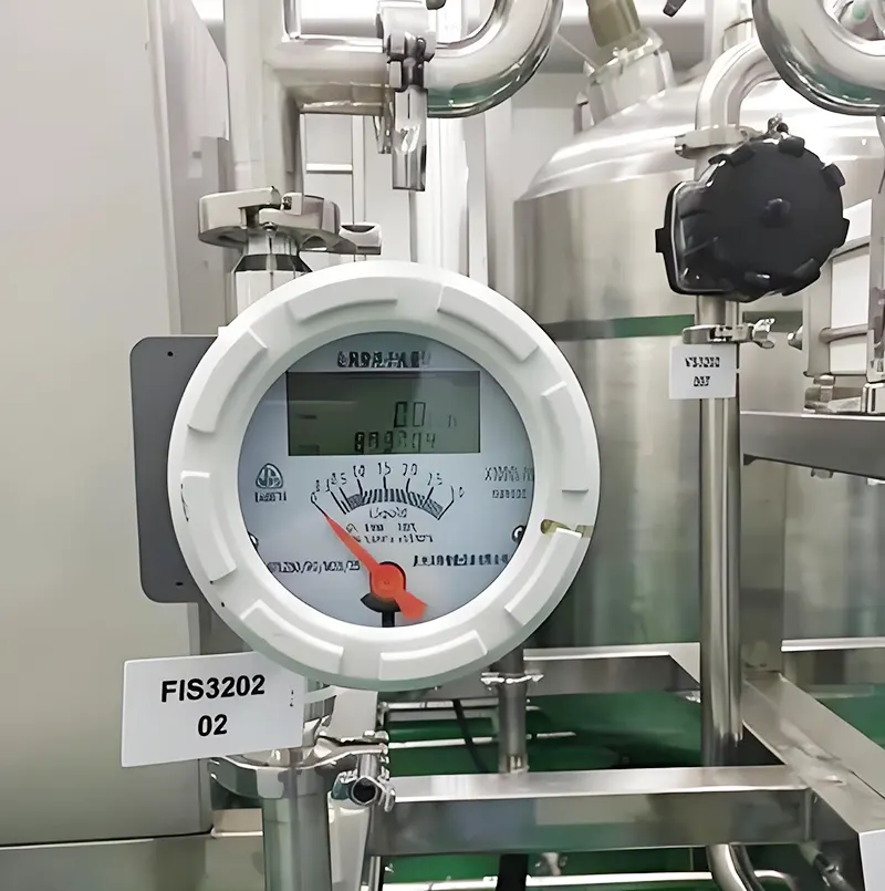
Rotameters used in Sanitary process flow measurement
Key Point:
For applications requiring only threshold monitoring (high/low flow alarms), simple rotameter designs are often the most cost-effective solution.
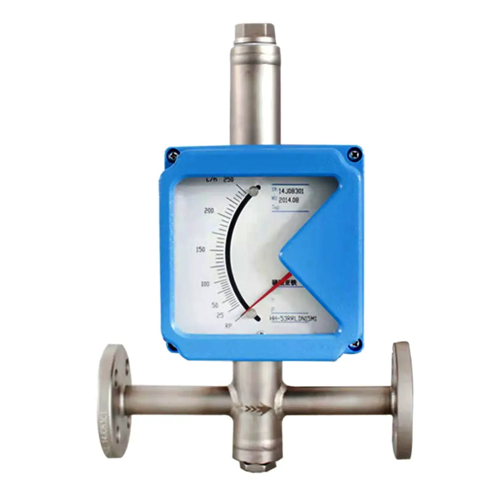
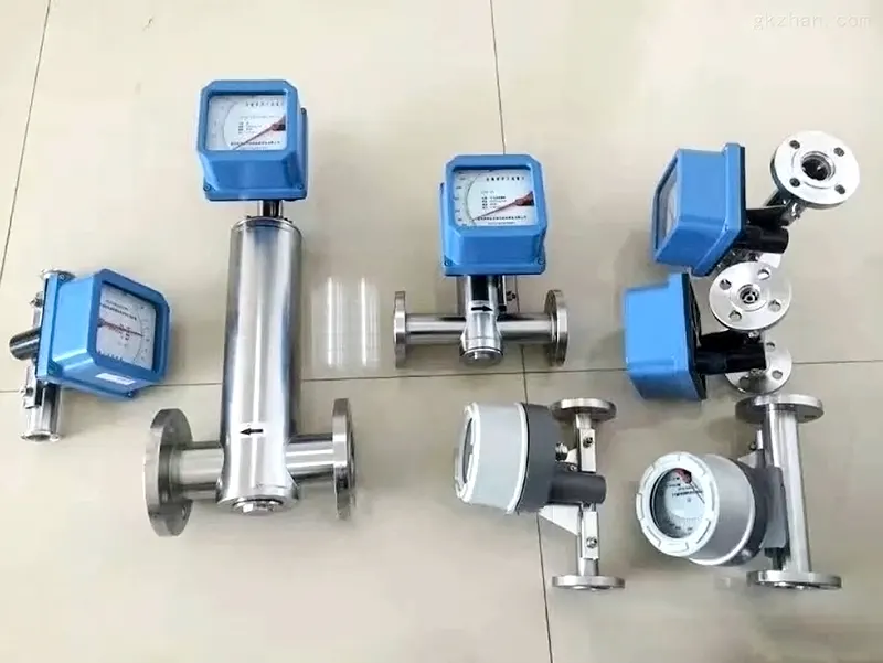
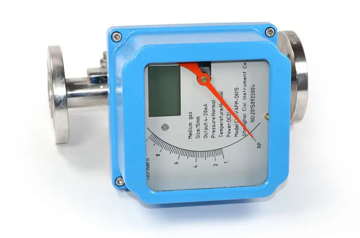
Metal tube rotameters with tramsmitters are commonly used in process industries as flow control detection instruments or for pipeline mixing and ratio adjustment. For example, in water treatment process control, they regulate the dosing ratio of chemicals into raw water.
4. Choosing Between Glass Tube and Metal Tube Rotameters?
The primary measurement targets of rotameters are single-phase liquids or gases. They are typically unsuitable for liquids containing solid particles or gases with liquid droplets, as particles adhering to the float or tiny bubbles in the fluid can affect measurement accuracy. For example, in micro-flow meters, even an imperceptible layer of deposits on the float may cause a deviation of several percent in the flow reading over time.
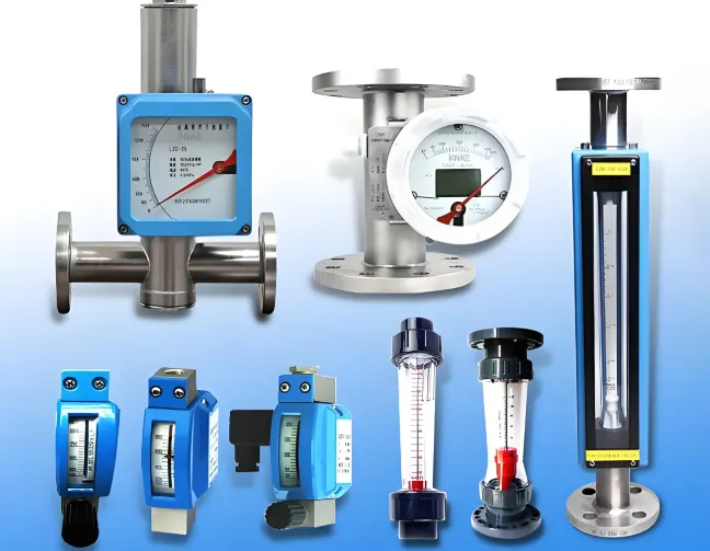
For cost-sensitive applications (low priced flowmeter) requiring only local indication, a glass tube rotameter is the first choice. If the temperature or pressure exceeds the limits of a glass tube, a metal tube rotameter with local indication should be used.
Glass tube rotameters should be equipped with a transparent protective cover to contain fluid splashes in case of tube breakage, allowing for emergency response.
For gas measurement, models with guide rods or ribbed guiding structures should be selected to prevent accidental float impact damage to the tapered tube. If remote signal output is needed for totalization or flow control, a metal tube rotameter with electrical signal output is typically used.
In hazardous (explosive) environments, if pneumatic control systems are available, a pneumatic transmission metal tube rotameter is preferred. If an electrical transmission model is required, it must be explosion-proof.
Metal tube rotameters are commonly used for opaque liquids. Alternatively, a glass tube rotameter with a ribbed (profiled) tapered tube can be selected, where the float position is determined by observing the contact marks between the float’s maximum diameter and the guiding ribs.
For measuring high-viscosity liquids at temperatures above ambient or liquids prone to crystallization/solidification upon cooling, a jacketed metal tube rotameter should be selected.
Metal tube rotameters are more robust than glass tube rotameters
Here is a table for summary between glass tube rotameter and metal tube rotameter
|
Selection Factor
|
Glass Tube Rotameter
|
Metal Tube Rotameter
|
|
Pressure Rating
|
≤1.0 MPa
|
Up to 42 MPa (ASME 300#)
|
|
Temperature Range
|
-20°C to 120°C
|
-80°C to 400°C
|
|
Media Visibility
|
Transparent fluids only
|
Opaque/hazardous fluids
|
|
Output Options
|
Local indication only
|
4-20mA/HART/Profibus
|
|
Hazardous Areas
|
Not suitable
|
Exd or Exia
|
|
Cost
|
Lower initial cost
|
Higher investment
|
5. How to sizing the rotameters ?
5.1 Selection of Flow Range Based on Actual Medium Density
Density is important to choose proper rotametrers
The term "actual medium density in operating conditions" refers to the in-situ density for liquids and the density of gases under operating conditions (or the standard-state density corrected for pressure and temperature). Typically, the flow range marked on the instrument is calibrated as follows:
For liquids: Based on water at normal temperature.
For gases: Based on air, converted to standard engineering conditions (20°C, 0.10133 MPa).
To select the appropriate flow range and meter size, the actual operating density must be converted using Equation (1) or (2). However, this adjustment is valid only if the viscosity of the medium is close to that of the calibration medium—meaning the coefficient (α) remain constant.
Liquids

(1)
In the formula:
— Maximum flow rate of the water-calibrated meter to be selected, L/h;
Q — Maximum flow rate of the liquid to be measured, L/h;
— Float density, g/cm³. For hollow floats , represents float mass (g) and V represents float volume (cm³);
, — Densities of the measured liquid and water, g/cm³.
Gases

(2)
In the formula:
— Maximum flow rate of the air-calibrated meter to be selected, m³/h;
Q — Maximum flow rate of the gas to be measured, m³/h;
— Density of the measured gas at standard conditions, kg/m³;
P — Absolute pressure of the measured gas at operating conditions, MPa;
T — Thermodynamic temperature of the measured gas at operating conditions, K.
5.2 Viscosity Effects and Float Selection
Liquid viscosity information also needs to be provided to choose rotameter
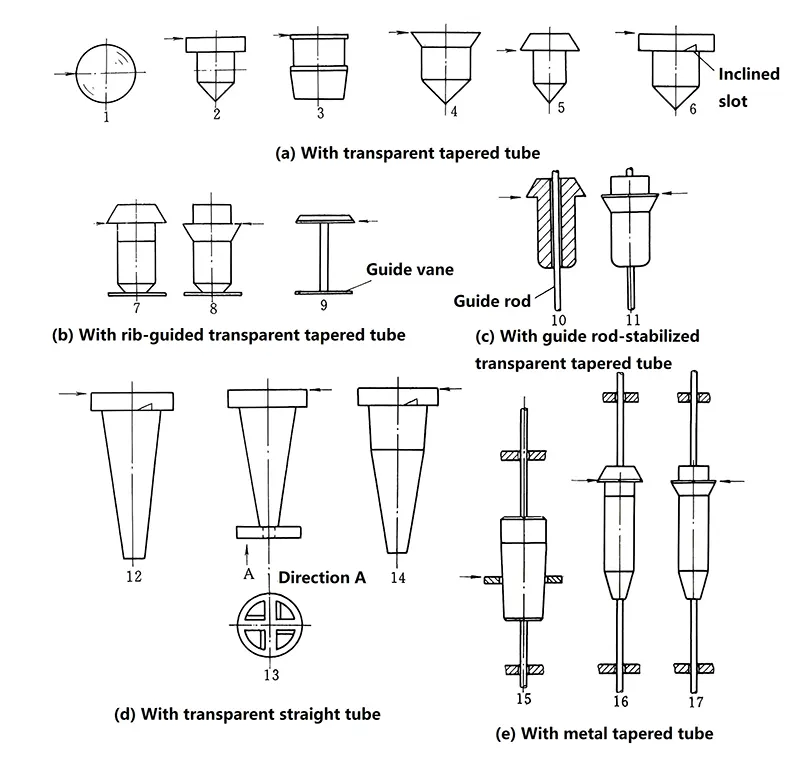
The selection of float shape is not within the user's discretion, as rotameter manufacturers design it based on the instrument structure and required flow range. Typical float configurations are illustrated in Figure 1. However, users should understand the characteristics of their specific float design and how fluid viscosity affects flow measurement accuracy.
Figure 1 Float shapes
In Figure 1, the arrow indicates the flow reading position or measurement reference point:
In Figure 1, the arrow indicates the flow reading position (or flow measurement reference point).
Spherical float (1): Typically used in small transparent tapered tube meters (DN6–DN10).
Floats (6, 12, 13, 14): Feature inclined slots or perforated guide vanes at their maximum diameter, causing them to rotate along their axis during measurement.
Float 6 was previously common in medical respiratory monitoring but is now rarely used in industrial applications.
Float 3: The heaviest among types (a), (b), and (c), enabling the highest flow capacity.
Float 9: The lightest, resulting in the lowest pressure drop, making it ideal for gas flow measurement.
Tapered float (14, also called "float plug"): Features two different taper angles, extending the scale length at 10%–20% of full-scale flow for enhanced low-flow sensitivity. This design is widely used in water treatment systems (e.g., softening devices).|
The fundamental flow equation does not explicitly incorporate fluid viscosity as a parameter. However, the flow coefficient α ceases to remain constant and becomes dependent on the annular Reynolds number (Re(annular)) when it falls below certain critical values. Since Re(annular) is inversely proportional to fluid viscosity, this establishes an indirect viscosity dependence.
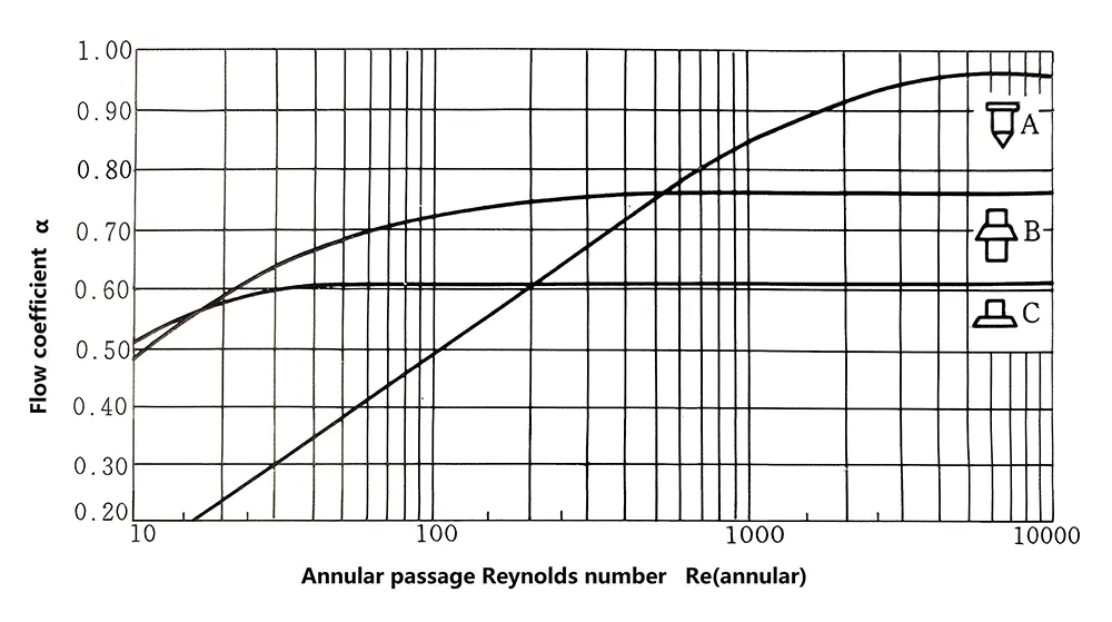 Figure 2 Relationship between Reynolds number and flow coefficient
Figure 2 presents the characteristic Re(annular)-α correlation curves for three distinct float geometries. The annular Reynolds number is determined by fluid viscosity, ratio of the float's maximum diameter to the local tapered tube diameter, and flow velocity in the annular passage.
For a properly designed and operational flowmeter, the fluid viscosity becomes the predominant factor affecting the annular Reynolds number (Re(annular)).
The constant flow coefficient (α) values, independent of Re(annular), are:
Type A float: 0.96
Type B float: 0.76
Type C float: 0.61
Additionally, the commonly used spherical float demonstrates an α value of approximately 0.99.
Significant variations in the flow coefficient are observed across different float geometries. The critical lower limits of Re(annular) for maintaining constant α are:
Type A float: about 6000
Type B float: about 300
Type C float: about 40.
For a flowmeter with a fixed nominal diameter and predetermined flow range (thus having a defined viscosity threshold), the flow reading will remain unaffected by fluid viscosity as long as the actual viscosity stays below this upper limit. Therefore, viscosity verification against this threshold value is essential during instrument selection.
Heating jacket rotameters can reduce fluids viscosity
There exist two distinct design approaches among different models:
Some rotameter models maintain identical float geometries across varying flow ranges within the same nominal diameter, achieving flow adjustment through weight variations of the float. Consequently similar viscosity threshold values.
Other models employ fundamentally different float shapes, resulting in distinct hydrodynamic profiles. Consequently different viscosity threshold limits.
Some variable area flow meter manufacturers provide the viscosity upper limit values of their instruments in product samples, user manuals, or instrument selection guides. Some also used to include viscosity correction curve charts, though such curves have become less common in recent years. Instead, users are now required to consult the manufacturers, who provide computer-calculated correction values based on the fluid viscosity and other physical properties specified by the user. In China, however, only some manufacturers offer viscosity upper limits or viscosity corrections, while many do not provide such data.
The hammer-type floaters (Floaters No. 12, 13, 14, and 15 in Figure 1) are significantly affected by fluid viscosity. Since liquid viscosity varies greatly among different liquids, special attention must be paid during selection. Even minor viscosity changes can have a considerable impact—for example, when water temperature rises from 5°C to 40°C at room temperature, its kinematic viscosity decreases from 1.52×10⁻⁶ m²/s to 0.66×10⁻⁶ m²/s.
For LZB-type glass tube rotameters with 15–40 mm diameters (Floater No. 3 in Figure 1), the temperature-induced error (primarily due to viscosity changes) falls within 0.1%–0.25% per °C. However, for 6 mm diameter meters, this effect can reach around 1% per °C.
When used with gases, except for hydrogen and helium, the kinematic viscosity differences between various gases and air are negligible. Therefore, viscosity has little effect on flow readings—except in small-bore, low-flow meters (e.g., a 6 mm meter used with helium may show 10%–30% lower viscosity impact than air after gas density correction). In most cases, viscosity’s influence on flow indication can be disregarded.
5.3 Scale Division, Accuracy, and Rangeability
Direct reading rotameters
Direct-reading flowmeters feature four types of flow indication scales: Dt/d ratio scale, percentage scale, direct flow rate scale, and millimeter scale.
ratio scale expresses the ratio of the float diameter (d) to the corresponding tube diameter (). This method is rarely used in domestic products.
Percentage scale displays the flow rate as a percentage of the full-scale value (100%). Its advantage is ease of conversion when fluid properties or operating conditions change.
Direct flow rate scale is calibrated for specified fluid conditions (typically water for liquids and air for gases). While this provides intuitive readings, it becomes less convenient than the percentage scale when actual conditions deviate from calibration conditions, requiring conversion.
Millimeter scale measures float height, which is then cross-referenced with an accompanying curve or data table to determine flow rate. This is typically used in applications where only the float’s position (rather than an exact flow value) needs to be monitored.
Some models combine both millimeter and direct flow rate scales for dual functionality.
The rotameter is an instrument with low to medium accuracy. For general-purpose glass tube rotameters, the basic error is 2.5%~5% FS for diameters smaller than 6 mm, 2.5% FS for 10~15 mm, and 1%~2.5% FS for 25 mm and above. Metal tube rotameters have a basic error of 1%~2.5% FS for local indication types and 1%~4% FS for remote transmission types. Corrosion-resistant models exhibit even lower accuracy. Some special-structure instruments, such as short-type glass tube rotameters with a scale length of only 2~3 times the float diameter and high-pressure blow-through metal tube rotameters, have an accuracy class as low as 5~10.
The rangeability of most glass tube rotameters is 10:1, while short-tube models and those with a diameter of 100 mm have a rangeability of 5:1. Metal tube rotameters typically offer a rangeability of (5:1)~(10:1).
5.4 Fluid Pressure, Temperature, and Pressure Loss of the RotaMeter
The working pressure and temperature of the measured fluid should be lower than the rated values of the meter. For fluids at higher temperatures, some manufacturers specify a reduction in the rated pressure, which is usually indicated in product catalogs and user manuals. Glass tube rotameters should not be used for high-pressure gases or high-pressure liquids exceeding their boiling point; instead, metal tube rotameters should be selected.
Glass tube rotameters have relatively low pressure loss, typically 0.2–2 kPa for small diameters and 2–8 kPa for 10–100 mm models. Metal tube rotameters exhibit slightly higher pressure loss, generally 2–8 kPa, with some models reaching 18–25 kPa. Pressure loss data should be listed in product catalogs and user manuals, though this information is often omitted.
The minimum operating pressure of the fluid should be several times higher than the pressure loss. For gases, excessively low pressure can easily cause float pulsation. Some instrument manuals specify the minimum fluid pressure requirement, while others recommend that the minimum operating pressure for liquids should be at least 2 times the pressure loss, and 5 times for gases.
6. Rotameter Installation and Usage Considerations
6.1 Flow meter direction
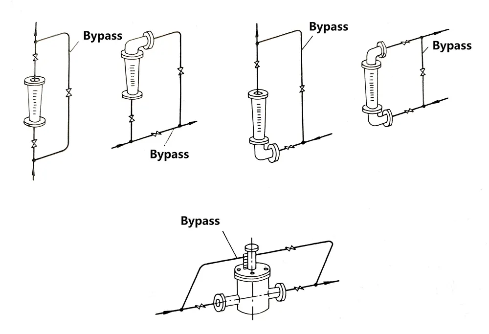
The majority of rotameters must be installed vertically on vibration-free pipelines, with no significant tilting, ensuring the fluid flows upward through the meter. Figure 3 illustrates a typical pipeline connection setup, including a bypass system for maintenance without flow interruption. The angle (θ) between the rotameter’s centerline and the vertical plumb line should generally not exceed 5°. For high-precision models (accuracy class 1.5 or higher), θ ≤ 2° is required. A tilt angle of θ = 12° can introduce an additional 1% measurement error.
Unlike other flowmeters, rotameters do not strictly require long upstream straight pipe sections. Some manufacturers may recommend (2–5)D lengths, but in practice, this is rarely necessary.
Figure 3 Example of pipeline connection
However, silverinstruments.com offer other flow direction rotameters ,such as horizontal rotameters or flow direction from top to bottom. Welcome to contact silverinstruments.com to obtain more technical details.
Horizontal rotameters from silverinstruments.com
6.2 Installation for dirty fluids flow measurement
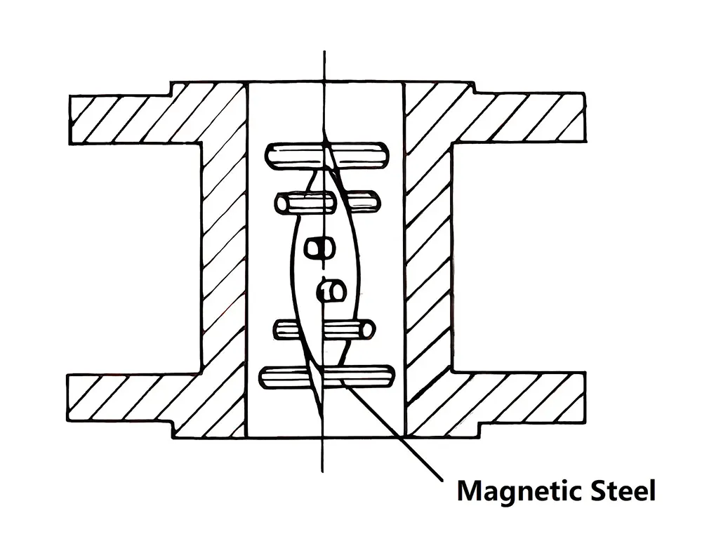
A filter must be installed upstream of the flowmeter.For metal tube rotameters with magnetic couplings handling fluids potentially containing ferromagnetic particles, a magnetic filter (as shown in Figure 4) must be installed upstream.
Maintaining cleanliness of both float and tapered tube is critical, particularly for small-bore instruments where even minor contamination significantly affects measurement accuracy.
Figure 4. Magnetic filter assembly
The cleanliness of both the float and tapered tube must be maintained, especially for small-bore meters, as even minor contamination can significantly affect measurement accuracy.
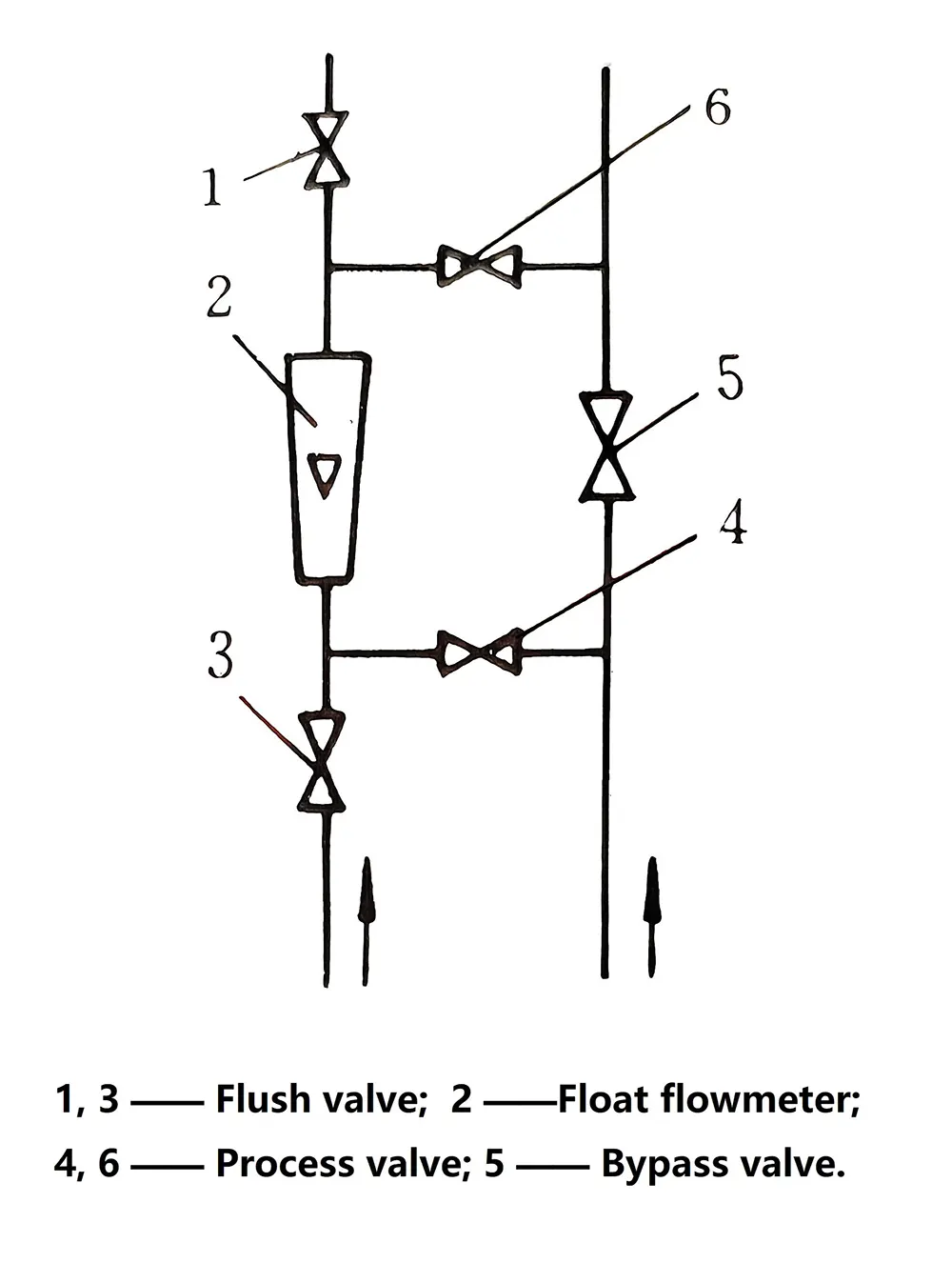
For example, in a 6mm diameter glass tube rotameter measuring seemingly clean water in the laboratory, with a flow rate of 2.5 L/h, after 24 hours of operation, the flow indication value increases by a few percent due to invisible contaminants adhering to the float surface. Removing the float and wiping it with gauze restores the original flow indication value. If necessary, a flushing piping can be installed as shown in Figure 5 for periodic flushing.
Figure 5 Flushing pipeline configuration
6.3 Installation for Pulsating Flow
If the flow itself is pulsating—such as when there is a reciprocating pump or control valve upstream of the intended meter location, or significant load variations downstream—the measurement position should be changed, or the piping system should be modified with compensatory measures, such as adding a buffer tank.
If the pulsation is caused by the meter itself—such as excessively low gas pressure during measurement, an upstream valve not being fully open, or a control valve not being installed downstream of the meter—targeted improvements should be made to mitigate the issue. Alternatively, a meter with a damping mechanism can be selected.
6.4 Installation for Extended Rangeability
When the required flow measurement range is wide (with a rangeability exceeding 10), it is common to use two or more glass tube rotameters with different flow ranges in parallel. Depending on the measured flow rate, one or multiple meters can be selected for series operation—using the smaller-range meter for low flow rates and the larger-range meter for high flow rates.
The series connection method is simpler to operate than parallel setups, as it eliminates the need for frequent valve switching. However, it results in higher pressure loss.
Alternatively, a single meter can be equipped with two floats of different shapes and weights—using the lighter float for low flow readings and switching to the heavier float once it reaches the top. This method can extend the rangeability to 50–100.
6.5 Eliminating Gas Entrapment in Liquid Measurement
For angular metal tube rotameters with non-linear inlet/outlet connections, special attention must be paid to ensure no residual air remains inside the extension sleeve that transmits float displacement—especially when measuring liquids. If the liquid contains micro-bubbles, they can easily accumulate in the sleeve, making regular venting essential.
This is particularly critical for small-bore flowmeters, as trapped gas can significantly affect flow measurement accuracy.
6.6 Necessary Conversion of Flow Values
Unless the flowmeter is specifically customized by the manufacturer based on the actual medium parameters (such as density and viscosity), liquid flowmeters are typically calibrated with water, while gas flowmeters are calibrated with air—with set values under standard engineering conditions.
When the fluid density, gas pressure, or temperature in the actual operating conditions differs from the calibration standards, necessary conversions must be performed. Detailed conversion formulas and methods can be obtained from silverinstruments.com
6.7 Calibration and Verification of Rotameters
For rotameters, liquid calibration/verification typically employs the standard meter method, volumetric method, or gravimetric method, while gas calibration commonly uses the bell prover method, with the soap film method applied for low flow rates.
Some international manufacturers have adopted dry calibration for mass-produced units. This involves precisely controlling the dimensions of the tapered tube and the weight/size of the float to indirectly determine flow values, thereby reducing costs. Only high-precision instruments undergo actual flow calibration. Domestic manufacturers also rigorously control the initial inner diameter, taper angle of the tube, and float dimensions, with actual flow verification primarily serving to inspect the inner surface quality of the tapered tube.
Instruments produced by such manufacturers feature interchangeable tapered tubes and floats, eliminating the need for complete assembly replacement.
The master flow meter method is a highly efficient calibration approach favored by manufacturers. Some manufacturers enhance this method by dividing a specific flow range into multiple segments using tapered glass tube rotameters with smaller taper angles. This extends the scale length of the standard meter and improves its accuracy, enabling high-precision and high-efficiency calibration.
Rotameters calibration
6.8 Troubleshooting
1) The actual flow rate does not match the indicated value
First, if the weight, volume, or maximum diameter of the float or tapered tube changes due to corrosion, or if the inner diameter of the tapered tube is altered, the solution is to replace them with corrosion-resistant materials. It should be noted that if the replaced float has the same dimensions as the original, recalibration can be performed based on the new weight and density. However, if the dimensions also differ, complete recalibration is mandatory. Additionally, if the cylindrical surface of the float’s maximum diameter becomes rough due to wear, it will significantly affect measurement accuracy, necessitating replacement with a new float. For floats made of or coated with engineering plastics, swelling may occur, altering the maximum diameter and volume. In such cases, floats made of more suitable materials should be used.
Second, if scale, dirt, or other contaminants adhere to the float or tapered tube, measurement accuracy will be compromised. In this situation, thorough cleaning of the float and tapered tube is required. However, care must be taken during cleaning to avoid damaging the inner surface of the tapered tube and the cylindrical surface of the float, ensuring their original smoothness is preserved.
Furthermore, changes in liquid properties may also lead to measurement deviations. If the actual density, viscosity, or other parameters of the liquid differ from the design specifications, the flow rate must be corrected or reevaluated based on the new parameters. Similarly, for gases, steam, or compressible fluids, variations in temperature and pressure can significantly impact flow measurement. Therefore, conversion and correction must be performed according to the new operating conditions.
If flow pulsation or rapid gas pressure fluctuations cause unstable readings, occasional float movement may have minimal impact. However, in cases of periodic oscillation, a damping device should be installed in the pipeline system, or an instrument with a damping mechanism should be adopted to enhance stability.
Moreover, the presence of bubbles in liquids or droplets in gases can alter fluid density, thereby affecting measurement results. Thus, necessary measures must be taken to eliminate these interferences.
Finally, when measuring liquid flow, if gas becomes trapped in dead zones inside the instrument, it can interfere with the float’s buoyancy. This effect is particularly pronounced in small-flow meters or during low-flow operation. Therefore, trapped gas must be promptly removed to ensure measurement accuracy.
In summary, appropriate countermeasures—such as material replacement, component cleaning, parameter correction, and system optimization—should be implemented depending on the specific cause to guarantee the accuracy and stability of flow measurement.
2) Flow fluctuations with sluggish float or pointer movement
When the flow rate changes but the float or pointer responds sluggishly, several factors may be responsible, each requiring specific corrective actions.
One primary cause is the presence of foreign particles between the float and guide shaft or a bent guide shaft, which can impede movement. To resolve this, the assembly should be disassembled, cleaned, and any debris or hardened deposits removed. If the guide shaft is bent—often due to rapid electromagnetic valve actuation causing abrupt float movement—it should be straightened. Additionally, adjusting the valve operation to reduce sudden flow changes can prevent recurrence.
Another common issue is the accumulation of iron powder or particles around the magnets in magnetic coupling float assemblies. This can be addressed by disassembling the unit and cleaning the affected components. During initial operation, flushing the pipeline via a bypass (without fluid passing through the flowmeter) helps remove contaminants. To prevent long-term rust buildup in the pipeline, installing a magnetic filter upstream of the meter is recommended.
In some cases, the linkage mechanism or pointer in the indicator section may become stuck. Manually moving the magnetically coupled linkage can help identify binding points, which should then be adjusted. Additionally, the rotating shaft and bearings should be inspected for obstructions—any debris should be cleared, or worn parts replaced.
For flowmeters with plastic components, swelling of engineering plastic floats, tapered tubes, or linings—or thermal expansion—can cause jamming. The solution is to replace these parts with materials resistant to the measured medium. For high-temperature applications, metal components are preferable over plastic to avoid deformation.
Lastly, weakened magnetic coupling due to degraded magnets can hinder proper float-to-pointer synchronization. To diagnose this, the meter should be removed, and the float moved manually to check if the pointer follows smoothly. If movement is inconsistent, the magnets must be recharged or replaced. To prevent magnetic degradation, impacts between coupled components should be avoided.
In summary, sluggish float or pointer response can stem from mechanical obstructions, magnetic interference, material degradation, or weakened couplings. Appropriate troubleshooting—such as cleaning, part replacement, or operational adjustments—ensures accurate and responsive flow measurement.
Here is simple table to explain
|
Symptom
|
Possible Causes
|
Corrective Actions
|
|
Flow reading drift
|
Float contamination
|
Clean with lint-free cloth
|
|
Pointer sticking
|
Magnet degradation
|
Recharge/replace magnets
|
|
Erratic float movement
|
Pulsating flow
|
Install dampener
|
|
Zero drift
|
Gas entrapment (liquids)
|
Vent the meter
|


 (1)
(1)
 (2)
(2)
