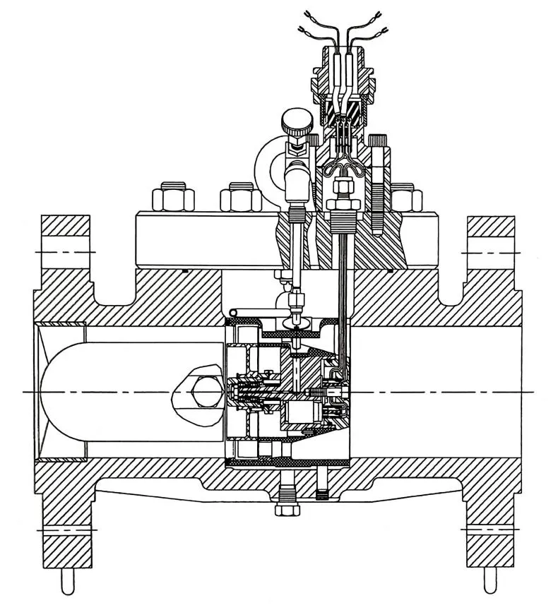
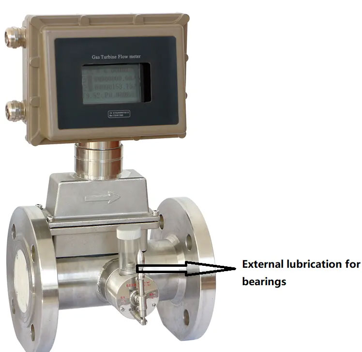
(Reproduced with permission from Nederlands Meetinstituut, van der Grinten, 1990):
How to install gas turbine flow meter properly ?
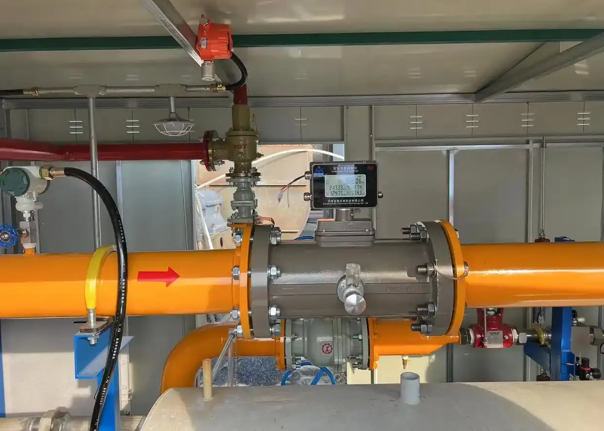
Proper install to achieve best flow measurement result
Research conducted by the British Gas Engineering Research Station confirmed that this type of flowmeter exhibits remarkable insensitivity to flow disturbances, making upstream or downstream straight pipe runs necessary in most practical installations (Fenwick and Jepson, 1975; cf. Harriger, 1966). The primary reasons include:
1. Reduced vorticity in large-diameter annular pipes, attributable to both angular momentum conservation and the flow conditioner's rectifying effect;
2.Significant flow contraction occurring in small-diameter piping sections;
3.Integral effects arising from the linear relationship between lift coefficient and small angles of incidence.
They concluded that flow conditioners should only be deployed in the inlet section if vortices are present upstream.
Van der Kam and Dam (1993) concluded that installing inlet flow conditioners can effectively reduce vortex flow. For example, the measurement error caused by two elbows installed in different planes (with 40°swirl angle) would not exceed 0.3%. Variations in pipe diameter upstream of the flowmeter are relatively unimportant. In extreme cases, a tube bundle flow straightener is sufficient. Surface roughness does not affect performance. Temperature effects within a 20℃ range are minimal but difficult to verify due to lack of necessary control measurement methods. Turbine flowmeters are not suitable for wet or dirty gas flows. The gas should remain clean, free of liquids and dust, and a filter with minimum 5μm rating should be used when necessary. The upstream pipeline must be thoroughly cleaned before installation (Bonner, 1993; ISO 9951).
According to Harriger's (1966) research, a combined installation method can be adopted, where the upstream 4D-length pipeline consists of a 2D flow conditioner and a 2D straight pipe section. However, swirl flow and pulsation can cause significant effects. Flowmeters with built-in flow conditioners can eliminate the influence of swirl flow. If pipe fittings are located within 5D upstream of the flowmeter, it is necessary to install straightening vanes. During flowmeter installation, careful alignment with the pipeline is required, and there should be no protrusions within the upstream 5D section. The downstream pipeline should maintain constant diameter without additional restrictions.
Enough straight pipelines before and after gas turbine flow meter
Van der Kam and van Dellen (1991) found that for 12 inches gas turbine flowmeters, an upstream distance of 10D is sufficient to ensure proper operation under allowable conditions, while 15D is required when swirl flow is present.
Mickan et al. (1996a, 1996b) and Wendt et al. (1996) experimentally investigated the velocity distribution in pipelines and its effects on gas turbine flowmeters. The studies employed laser Doppler measurement techniques and examined the impact of various installation configurations on vortex flowmeter performance, including:1.Flow conditioners; 2.Single elbow installations; 3.Dual non-coplanar elbows; 4.50% flow blockage between elbows.
Interested readers may refer to the original publications. While most experimental errors remained below 1%, this was not universally observed across all test conditions.
George (2002) examined advancements in turbine flowmeter technology within the revised AGA Report No.7. The study identified two significant developments since 1996: dual-rotor designs and extended-range flowmeters. Key findings include:
• For short-coupled, close-proximity, swirl-coupled, and pure swirl flow conditions, four co-calibrated instruments demonstrated measurement errors within ±1%;
• Properly integrated flow conditioners at the meter inlet can reduce deviations to ±0.25%;
• Single versus dual-rotor configurations showed negligible impact on measurement bias;
• Pressure-induced variations require additional investigation.
Islam et al. (2003) reported experimental results of turbine flowmeters with integrated flow conditioners under disturbed airflow conditions.
Balla and Takaras (2003) documented an approximate 1% drift in gas flowmeter performance after one year of operation, potentially attributable to:
1.Liquid condensate accumulation
2.Residual contaminants from pipeline fabrication
Ullebust and Ekerhovd (2008) recommended the following maintenance protocols:
1.Pipeline internal surface roughness inspection
2.Flow conditioner integrity verification
3.Flowmeter alignment examination
4.Visual inspection procedures
Operational limitations:
• Temporary overspeed up to 20% is permissible (though sustained overspeed causes damage)
• Temperature monitoring within 2D downstream of the flowmeter is required (manufacturer-specified range: -10 to 50°C)
• Mandatory gas drying when process conditions lead to liquid condensation in pipelines
Detection and monitoring
The most common method for measuring turbine wheel speed involves using a gearbox, which may introduce resistance due to gear transmission losses. Additionally, resistance can be caused by electromagnetic coupling, flow display mechanisms, and calibration processes. The use of electromagnetic detection can significantly reduce such resistance.
For high-frequency signals, magnetic induction or proximity switches can be employed on aluminum blades, metal strips on the hub, or driven disks of the main shaft to extract signals based on the switching effect, achieving a measurement frequency of up to 3 kHz. For applications requiring 1 to 10 pulses per revolution, reed switches or slot sensors may be used.
Reeb and Joachim (2002) developed an online monitoring tool for gas turbine flowmeters named AccuLERT G-II (FMC Measurement Solutions), which claims to detect and analyze both mechanical and fluid-related errors.
AccuLERTcan monitor rise time ratio, fall-time ratio, and standard deviation. In addition, it can also monitor key variables such as flow rate, time, and changes during operation to estimate the operating status of the flowmeter.
Unstable fluids
Gas turbine flowmeters are susceptible to pulsating flow conditions. When fluid accelerates, the increased incidence angle on turbine blades causes faster rotor acceleration. Conversely, decelerating flow may lead to blade stalling with minimal drag resistance, resulting in overall flow overestimation. Prolonged measurement of highly pulsating flows can cause bearing damage in turbine assemblies.
Head (1956) established the pulsation coefficient for turbine flowmeters, defined as:
q
i/q
V =(1+αbΓ²)
Where
qi is the flow rate displayed by the meter,
qV is the actual flow rate, (α=1/8 represents the sinusoidal variation law of the fluid, b can be considered as 1 for non following flow meters, and Γ is full-flow regime amplitude relative to mean velocity. Head believes that Γ=0.1 is the critical value for significant errors.
The speed attenuation curve without fluid can be obtained from transient analysis, as shown in Figure 3.The figure allows determination of rotor deceleration time to standstill and terminal slope of the decay curve.This slope is physically correlated with the drag-to-inertial force ratio under zero-flow conditions, serving as a diagnostic indicator for bearing condition.
However, de Jong and van der Kam (1993) questioned its credibility under high-pressure conditions. Readers can also refer to the article by Lee and Evans (1970), which describes how they obtained the speed attenuation curve using an external mechanical friction load method and provided typical values of inertia force. For example, for a 150mm low-pressure flowmeter, the rotational inertia of the plastic rotor is I=0.242×10⁻³kg⋅m³,and the rotational inertia of the aluminum high-pressure rotor is I=0.486×10⁻³kg ⋅m³. They also considered the variation of leaves with a value of η=0.2.
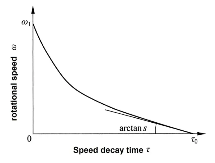
Figure 3 Rotational speed decay curve of freely rotating flowmeter
during spin-down test
(Reproduced with permission from ASME, after Lee and Evans, 1970)
Lee et al. (1975) provided the error caused by sinusoidal fluctuations. Assuming the worst-case scenario, where the rotor cannot follow the pulse due to excessive inertia, an error of approximately 0.5% is obtained at a pulse index of 0.1, and an error of approximately 2% is obtained at 0.2, where the pulse index is
Γ=

Figure 4 is derived from the results of Fenwick and Jepson (1975), illustrating the effect of square-wave pulsations on turbine flowmeters. McKee (1992) found that the error was 0 at a 2% variation and exceeded 1.5% at 6% [Atkinson, 1992. Numerical calculation methods were employed to determine the errors introduced by approximately sinusoidal fluid pulsations in flowmeters. Cheesewright et al. (1996) raised concerns about the lack of reported data on pulsed waveforms.
Fenwick and Jepson (1975) conducted experiments by introducing a 60-second pulsed flow into a 100 mm flowmeter, resulting in measurements exceeding the actual flow rate by 40%.
Jungowski and Weiss (1996) tested a 100 mm flowmeter under pulsating air flow at frequencies ranging from 5 to 185 Hz. Their results showed that when the ratio of the root-mean-square velocity to the mean velocity was 0.1, the readings were overestimated by 1%, and when it was 0.2, the overestimation reached 4%.
Stoltenkamp et al. (2003) presented an interesting study, discussing the possibility of misleading turbine flowmeter readings caused by gas oscillations due to acoustic effects. They also proposed a theoretical model to explain the phenomenon.
I processed some experimental data where the natural gas flow rate transitioned from high to low, accompanied by sudden changes and significant errors—a behavior already predicted by Jepson and others in their methodology.
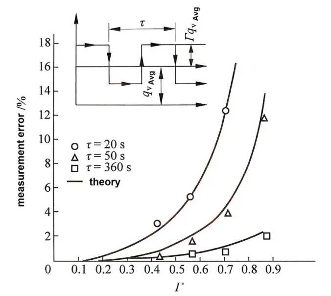
Figure 4 Effects of modulated flow in a
100 mm turbine flowmeter
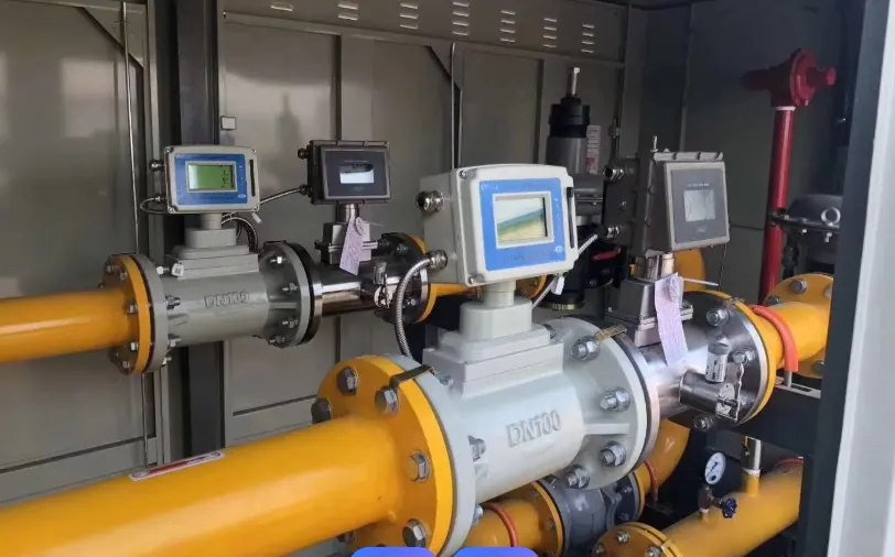
Where to use gas turbine flow meters?
Gas turbine flowmeter is suitable for all non-corrosive gases and fuel gases, including:
CO2 gas flow meter, town gas, natural gas, refinery gas, coke oven gas,
propane flow meter, butane flow meter, LPG/air mixtures, acetylene, ethane, nitrogen flow meter , carbon dioxide CO2, air, and all inert gases.
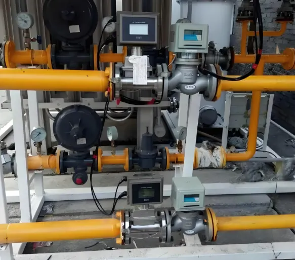
Gas turbine flow meters are measuring natural gas
Turbine flowmeters are generally not used for oxygen measurement due to the following reasons:
1. The lubricant must be non-reactive with oxygen.
2. The oxygen flow velocity in pipelines must not exceed 10 m/s, as higher speeds can cause pipeline oxidation—gas turbine flowmeters require even lower velocities.
Pfrehm (1981) adapted a widely accepted liquid flow measurement technique to develop a mass flow measurement method for ethylene gas. This method utilized a flowmeter, densitometer, flow computer, and a bidirectional piston prover. The claimed accuracy of this flowmeter was ±0.2%, with linearity maintained from 20% to 100% of full scale
Advantages and disadvantages
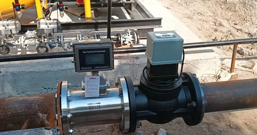
High precision gas turbine flow meter
1.Mechanical degradation or wear alters friction and blade geometry, reducing the flowmeter's adjustable range and causing reading deviations. Filtration can slow meter deterioration, and regular inspections are essential. A slow-down test can indicate bearing degradation.
2.Rapid fluid fluctuations cause over-reading. For example, a 10-minute on/10-minute off flow cycle may lead to a 3% overestimation.
3.Swirling flow distorts readings, necessitating a flow straightener.
4.Pressure variations and high bearing friction can introduce reading drift up to 2%.
5.Flowmeter failure does not compromise gas flow safety.
Additionally, van der Kam, Dam, and van Dellen (1990) discussed reliability, high precision, dual-rotor measurement, and bearing systems.
