

Vortex flow meter for compressed air
For compressed air media, additional attention should be paid: prioritize installing the flow meter after the dryer and in front of the air storage tank, and install a gas-liquid separator upstream to ensure that the air entering the flow meter is dry and free of liquid droplets; At the same time, do a good job of pipeline support and shock absorption to avoid the superposition of airflow pulsation and pipeline vibration affecting measurement stability.
The length of the upstream and downstream straight pipe sections of the flowmeter must strictly comply with the requirements of Table 1

Two 90 degree elbows on the same plane: upstream ≥ 25D, downstream ≥ 5D

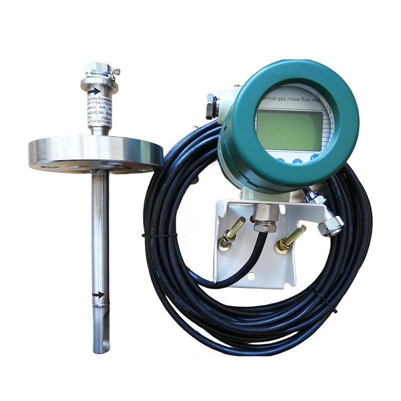
Thermal mass flow meter install for compressed air measurement
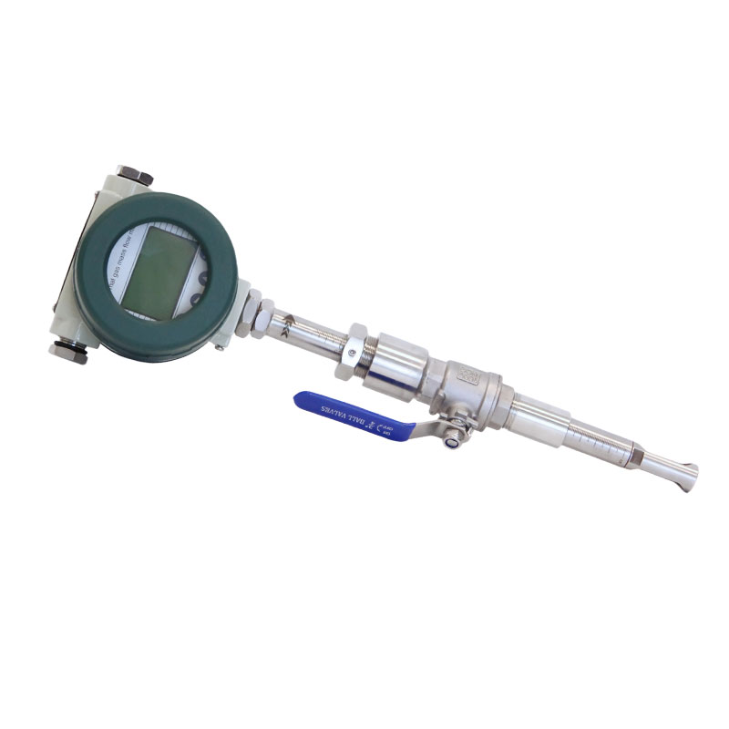
When the nominal diameter of the pipeline is ≤ DN50, pipeline installation is preferred, with optional of compressing fitting, thread or flange connection methods;
When the nominal diameter of the compressed air pipeline is greater than DN50 (2 inches), insertion type thermal mass flow meter installation is preferred, and threaded or flange connection methods can be selected.
If the on-site pipeline has been installed and no flange has been reserved for installation, insertion installation can be used. When ordering, the on-site working conditions must be clearly explained to the manufacturer.
Insertion installation steps:
Thermal gas flow meters have clear requirements for the state of compressed air medium to ensure measurement accuracy and instrument life:
Dryness requirement: Compressed air should be thoroughly dried and filtered to prevent liquid water, oil mist, or condensate from entering the flow meter. Liquid media can adhere to the surface of thermal sensors, changing their thermal conductivity characteristics, directly causing measurement distortion, and even permanent damage to the sensors.
Cleanliness requirement: Compressed air should remove solid particles, dust and other impurities to prevent them from depositing on the probe and sensor, affecting heat exchange efficiency, and avoiding local blockage of the pipeline.
Stability of working conditions: Measurement points should be selected as much as possible in pipe sections with small pressure and temperature fluctuations to avoid a decrease in measurement repeatability due to frequent changes in the compressed air state.
To ensure the accuracy and repeatability of compressed air measurement, the following straight pipe lengths (in multiples of the inner diameter D of the pipeline) need to be met according to the upstream interference type:
Upstream interference type: Upstream straight pipe section A, downstream straight pipe section B
|
Type of Upstream Disturbance |
Upstream Straight Run (A) |
Downstream Straight Run (B) |
|
Single 90° elbow or T-junction |
15D |
5D |
|
Two 90° elbows in the same plane |
21D |
5D |
|
Two 90° elbows in different planes |
40D |
10D |
|
Pipe diameter reduction |
15D |
5D |
|
Pipe diameter expansion |
30D |
10D |
|
Downstream of a valve |
40D |
5D |
During installation, priority should be given to selecting a location away from sources of interference such as valves, bends, and regulating valves to ensure stable fluid velocity distribution.

SRK-100 series Integral Display Thermal mass flow meter wiring
Remote display thermal mass flow meter structure: The sensor and digital display meter are connected using a three wire system and wired according to the marked color:

SRK-100 series Remote Display Thermal mass flow meter wiring
Red → Red: Positive pole of power supply


 English
  français
  Español
  русский
  português
  العربية
  tiếng việt
  Türkçe
  ไทย
ไทย  українська
  Malay
Malay  עברי
עברי  Indonesia
  Ελλάδα
  ಕನ್ನಡ
ಕನ್ನಡ  հայերեն


 Email
Email
 WA
WA
 Inquiry


