
English
Liquid turbine flow meter can measure clean liquids ,such as RO water, diesel, palm oil ,vegetiable oil and so on.By installing the turbine flow sensors you can get the best measuring result.This article is mainly tallking about how to install the turbine flow meter correctly .
Turbine flow meters should be installed at the place in compliance with the requirements below:
Flow Direction
All SILVER turbine flow meters are designed to measure flow in only one direction. The direction is indicated by the arrow on the body.
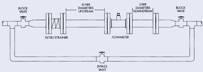
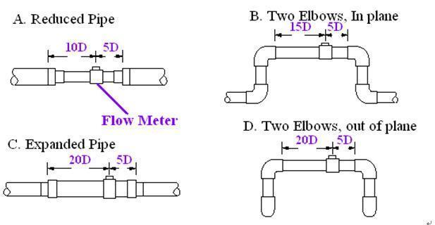
Required Lengths of Straight Runs
Flow altering device such as elbows, valves
and reducers can affect accuracy. See diagram for typical flow meter system
installation.
Warning:
Precaution is needed for direct sunshine and rain when the meter is installed outside.
Anti-Cavitation
Cavitation can be caused by entrained air, and it can seriously damage the rotor on a turbine flow meter. An amount higher than about 100 mg/l of entrained air or gas can produce error. In addition, cavitation can be caused by too little backpressure on the flow meter. For SILVER turbine flow meters, you should provide a backpressure (downstream pressure) of at least 1.25 times the vapor pressure, plus 2 times the pressure drop through the flow meter. See formula 1
Formula 1: Pb≥1.25×Pv + 2×(Pin –Pout)
In formula 1: (Pb: Back pressure; Pv: Vapor Pressure; Pin: Inlet Pressure; Pout: Outlet Pressure)
Create backpressure by installing a control valve on the downstream side of the meter at the proper distance detailed above.
Special Notice
Foreign material in the liquid being measured can clog the meter’s rotor and adversely affect accuracy. If this problem is anticipated or experienced, install screens to filter impurities from incoming liquids.
To ensure accurate measurement, drain all air from the system before use.
When the meter contains removable
coverplates. Leave the cover plate installed unless accessory modules specify
removal. Don’t remove the cover plates when the meter is powered or electrical
shock and explosion hazard can be caused.
Thread Process Connections
1. To protect against leakage, seal all threads with an appropriate sealing compound. Make sure the sealing compound does not intrude into the flow path.
2. Make sure the arrow on the outlet is pointed in the direction of the flow.
3. Tighten the turbine onto the fittings.
Use a wrench only on wrench flats.
Flange ProcessConnections
The flange follows GB/T 9113-2000 (ISO 7005-1) RF (Raised Face).
Note: flange can be customized following other criteria.
Use a gasket between the meter flange and mating flange. Determine the material of the gasket based on the operating conditions and type of fluid.
Note: Do not over tighten
the flange bolts. This may cause the gasket to be compressed in.
welcome to contact Silver Automation Instruments for turbine flow meter factory price.