
English
This article introduces the working principle and advantages of Coriolis force mass flowmeter, focusing on listing and analyzing some problems found in the use of Coriolis force mass flowmeter in various material measurement processes of Petrochemical Company. It also puts forward the issues that need to be paid attention to in the selection and installation of Coriolis force mass flowmeter, and discusses the influence of stress and pressure on Coriolis force mass flowmeter.
Introduction to Advanced Flow Measurement Technology
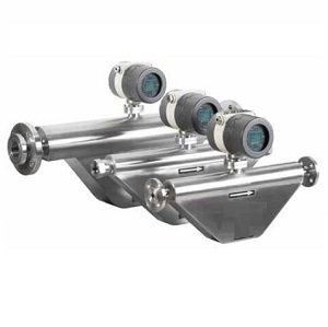
Coriolis force mass flowmeter is widely used in petrochemical and other fields, and is one of the most advanced flow measurement instruments in the world today.

Coriolis mass flow meter is popular in petrochemical industry
As a large refining and chemical enterprise, Jinxi Petrochemical Company mainly produces gasoline, kerosene, diesel, liquid hydrocarbons and other products. Coriolis mass flowmeter is reliable in the measurement process of these materials, especially for the measurement process of factory products, with an accuracy of less than 2 ‰, which improves the accuracy of energy and material flow measurement of Jinxi Petrochemical Company, avoids unnecessary losses, and ensures that the interests of the enterprise are not damaged.
For businesses seeking reliable Coriolis flow measurement solutions, companies like Silver Automation Instruments (silverinstruments.com) provide comprehensive mass flow meter product lines designed to meet the demanding requirements of petrochemical industry.
Silverinstruments.com provide complete line of Coriolis flow meter
Coriolis Mass Flow Meter (CMF) is a direct mass flow meter that utilizes the principle of Coriolis force, which is proportional to the mass flow rate, generated by the fluid in a rotating system while moving in a straight line.
As shown in Figure 1, when a particle with a mass of m moves at a velocity of υ in a pipeline rotating at an angular velocity of ω about the p-axis, the particle experiences two components of acceleration and force.
The Physics Behind the Measurement:
1) The normal acceleration, also known as the centripetal force acceleration α r, has a magnitude equal to ω 2r, Direction towards the P axis;
2) The tangential acceleration α t, also known as Coriolis acceleration, has a magnitude of 2 Ωυ and is perpendicular to α r. Due to composite motion, Coriolis Fc=2 Ωυ m acts on the particle in the α t direction, and the pipeline exerts a reverse force - Fc=-2 Ωυ m on the particle.
When a fluid with a density of ρ flows at a constant velocity υ in a rotating pipeline, any section of the pipeline with a length Δ x will experience a tangential Coriolis force of Δ Fc.

Figure 1.
Modern Implementation of Coriolis force
Therefore, directly or indirectly measuring the Coriolis force generated by the fluid flowing in a rotating pipeline can determine the mass flow rate, which is the basic principle of CMF.
However, it is difficult to generate Coriolis force through rotational motion. Currently, all products are generated by pipeline vibration, which means that a thin-walled measuring tube with two fixed ends is excited at the resonance or near resonance frequency (or its higher harmonic frequency) of the measuring tube at the midpoint. The fluid flowing inside the tube generates Coriolis force, causing opposite deflection in the front and rear halves of the measuring tube at the midpoint. The deflection amount is detected to obtain the mass flow rate.
The advantages of Coriolis force mass flowmeter mainly include the following aspects:
(1) Direct measurement of mass flow rate with high measurement accuracy; Unlike volumetric flowmeters (like turbine flow meters or vortex flow meters) requiring density compensation, Coriolis meters provide direct mass measurement with industry-leading precision.

Volumetric flow meter like vortex flow meter cannot directly measure mass flow
(2) Wide range of measurable fluids, including various liquids with high viscosity(like resin ,bitumen, crude oil) , slurries containing solids, liquids containing a small amount of uniformly distributed gas(gas content within 5%), and gases with sufficient density (gases with high pressure).

Coriolis flow meter for slurry flow measurement
(3) The amplitude of the measuring tube is small and can be considered as a non moving component; there are no obstructions or moving parts inside the measuring tube.
(4) Not sensitive to the distribution of upstream flow velocity, therefore there is no requirement for upstream and downstream straight pipe sections.
(5) The flow measurement value is insensitive to fluid viscosity, and the influence of fluid density on the flow measurement value is minimal.
(6) A mass flow meter can measure multiple parameters. The simultaneous measurement of mass flow rate can measure fluid density and temperature, as well as derive measurements of volumetric flow rate, solute concentration, and the content of different phases (or components) in liquid-solid two-phase fluids (or immiscible two-component liquids).

Multiple Parameters can be detected by Coriolis mass flow meter
Real-World Applications and Challenge Analysis in Petrochemical Operations
In recent years, with the increasing pursuit of cost control and increased efficiency by Jinxi Petrochemical Company, the requirements for energy and material measurement in the production and sales processes have also become higher. The company has continuously increased its efforts to update and transform energy and material measuring instruments, including the use of mass flow meters for measuring the mutual supply of crude oil and equipment materials.
Especially in terms of product delivery, high-precision Coriolis mass flow meters are used for gasoline, kerosene, diesel, liquefied gas, and propylene. Quality suppliers like Silver Instruments (silverinstruments.com) have supported these implementations with robust, field-proven Coriolis flow meter solutions specifically designed for petrochemical environments.

Coriolis flow meter can be used to measure gasoline, diesel, LPG, Kerosene and so on.
While mass flow meters offer exceptional performance, of course, various problems may arise during the use of mass flow meters. However, based on our analysis, we believe that the main causes of these problems in the measurement process of mass flow meters are improper installation of the flow meters and the influence of the physical properties and parameters of the measuring medium. In other words, they can be divided into two parts: the impact of external factors such as installation, and the impact of internal factors on the physical properties of the measuring medium.
Case Study - Loading Dock Installation Challenge:
In 2002, Jinxi Petrochemical's loading dock was equipped with six DN150 (6 inches) mass flow meters, which were used for measuring gasoline and diesel during loading. During the initial operation, one of the diesel flow meters often experienced a brief instantaneous flow of 5 to 7 tons without loading.
How to do zero point adjustment on Coriolis mass flow meter
Despite multiple on-site inspections and adjustments to the zero point, this phenomenon still occurred. Finally, the mass flow sensor was separated from the process pipeline and it was found that the flange on one side of the sensor was 3cm horizontally different from the flange connecting the process pipeline.
At that time, the installation team was not professional enough and the on-site commander lacked experience. In this case, the mass flow sensor was rigidly connected, and the pipeline stress acted on the sensor. In the case of strong sea winds, the flow meter often experienced a brief instantaneous flow of 5 to 7 tons, which affected the normal measurement of the flow meter.

Proper install to ensure correct operation of Coriolis flow meter
So, the installation of mass flow meters and factors such as on-site environment are the main factors that affect the normal measurement of Coriolis mass flow meters. This case demonstrates how installation quality and environmental factors critically impact flowmeter performance, making proper installation procedures and expert guidance essential for successful implementations.
During the installation process of the sensor, if the center of the pipeline connecting the flow sensor is not aligned (or parallel) or the pipeline temperature changes, pipeline stress will form pressure, tension, or shear forces that act on the alignment between the measuring pipes of the mass flowmeter, causing asymmetry of the detection probe and leading to zero-point drift.
Mitigation Strategies:
Therefore, during the installation of the mass flow meter, it is necessary to ensure that the center of the pipeline connected to the flow sensor is aligned. At the same time, in the case of large temperature changes, thermal expansion isolation fittings can be installed in the pipeline.
Real-World Example: The crude oil metering meter of Jinxi Petrochemical Distillation Unit is a Coriolis mass flow meter installed inside the unit and close to the pump room, causing significant vibration in the process pipeline. Therefore, there are some issues with the metering data of the flow meter, resulting in abnormal yield of the unit.
Solution Implementation: In this case, we have installed supports at both ends of the flow meter to reduce the impact of vibration and ensure its normal operation.

Better to have supports at both ends of mass flow meter
Mass flow meters can operate in vibration environments, but must be isolated from vibration.
Best Practices for Vibration Control:
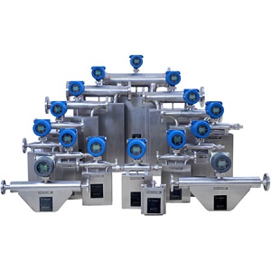
Especially in cases of high vibration, flexible pipes can be used to connect with the vibration tube and support frames can be used to isolate the vibration. But it is more important to prevent the vibration frequency from being the same as the operating frequency or harmonic frequency of the mass flowmeter. When multiple instruments of the same model are installed in series or parallel near the ground, especially when installed on the same support platform, the working frequency vibrations between the mass flow meters will affect each other, causing abnormal vibrations, and in severe cases, the instruments may not work.
The installation posture and position of the mass flow sensor are also very important for the normal operation of the flow meter. Residual solids inside the measuring tube and scaling on the tube wall can both affect measurement accuracy.
Installation Guidelines:

Of course, in some special cases, the installation method of mass flow sensors can still be changed. For example, due to the process pipeline of the crude oil metering mass flowmeter in Jinxi Petrochemical Distillation Unit, although it measures liquids, it adopts an upward installation method with the measuring tube. In this case, the outlet back pressure of the mass flowmeter needs to be high to ensure that the measuring tube is full. At the same time, attention should be paid to the problem of vibration to reduce the impact of vibration on the flowmeter measurement.
Shutoff Valve Requirements: In order to ensure that the measuring medium does not flow when the flow sensor is adjusted to zero, stop valves should be installed upstream and downstream of the mass flow meter, and ensure that the valves do not leak.
Control Valve Positioning:If a control valve needs to be installed, it should be installed downstream of the mass flow meter, which is beneficial for maintaining the highest possible static pressure of the mass flow meter to prevent the occurrence of cavitation and flash evaporation.
Case Study - Liquefied Gas Measurement Challenge:
There is a Coriolis mass flowmeter used in Jinxi Petrochemical's liquefied gas measurement, which always felt a large measurement deviation during the measurement process. A comprehensive inspection was conducted on the installation of the mass flowmeter, and no problems were found. The mass flowmeter was sent to the calibration department for calibration, and the results were qualified. However, after reinstallation, there were still problems with the measurement data of the mass flowmeter.

Fluids operation pressure should not be over than pressure rating of mass flow meter
Root Cause Analysis: In response to this situation, we compared the operating parameters of the on-site flowmeter with the calibration process parameters and found that the pressure of the liquefied gas on site was 1.6 MPa, while the pressure of the medium during the calibration process was about 0.3 MPa. Therefore, the change in the measured medium pressure affected the measurement of the mass flowmeter.
Technical Impact Explanation:In fact, the quality flowmeter should first consider that the measured medium pressure should not exceed the specified working pressure, and also consider the degree of influence of static pressure changes. The pressure changes affect the tightness of the measuring tube and the degree of Bourdon effect, as well as the original zero bias that destroys the asymmetry of the measuring tube. Although the variation of instrument constants and zero drift is small, the impact on high-precision instruments cannot be ignored when there is a significant difference in pressure and calibration during use.
Pressure Effect Correlation:
Authoritative Test Results: Independent testing of eight mass flowmeters demonstrated quantifiable pressure effects:
| Static pressure MPa | 2 | 2.4 | 2.8 | |
| Flow measurement error % | average | -2.21 | -3.25 | -0.375 |
| max | -1.57 | -2.55 | -2.6 | |
| min | -3.15 | -4 | -4.56 | |
| Note: The pressure during calibration shall prevail | ||||
The change in density of the measuring medium changes the quality of the flow measurement system, causing a change in the balance of the flow sensor and resulting in zero offset. If measuring a specific liquid, as long as it is zeroed under the actual liquid density conditions, the density change during use is not significant, and there is generally no problem.
Multi-Fluid Pipeline Challenges: However, measuring several liquids with significant density differences on a single pipeline can result in additional errors due to zero point variations, requiring careful consideration during system design and operation.
Coriolis force mass flowmeter can measure a wide range of liquid viscosity and exhibits good measurement performance. In fact, liquid viscosity can change the damping characteristics of the system, thereby affecting zero bias and having a certain degree of impact on flow measurement values at low flow rates.
Design Considerations: One of the main factors we consider when selecting the specifications and sizes of mass flow meters based on usage conditions is that the estimated instrument pressure loss is within the allowable range of the piping system. To achieve optimal measurement accuracy while allowing for pressure drop, the maximum flow rate used should be selected as high as possible within the flow range.

Pressure loss/viscosity Curve of SH-CMF Coriolis flow meter from silverinstruments.com
Viscosity-Pressure Drop Relationship: The pressure drop of a mass flowmeter increases with the increase of fluid viscosity, which means that an increase in viscosity will increase the pressure loss of the instrument. Coriolis mass flowmeter used for crude oil measurement in the distillation unit of Jinxi Petrochemical fully considered the factors of increased viscosity and pressure loss during the selection process, without affecting the operation of the process equipment.

Flow rate/ Accuracy/Pressure Drop of SH-CMF Series Coriolis flow meter from silverinstruments.com
There are many factors that currently affect the normal measurement of quality flow meters. Some of these factors require us to reinstall the flow meter, while others even require us to replace the flow meter. This requires us to comprehensively consider all aspects of the influencing factors in the selection process of quality flow meters in order to ensure their normal operation.
Maintenance and Calibration Requirements: In practical applications, there are many factors that cause zero drift, such as installation stress of sensors, structural asymmetry of measuring tubes, and changes in physical parameters of the measured fluid. This requires us to regularly check and adjust the zero point.
Next-Generation Technology Advances: At present, with the continuous advancement of measurement technology and the continuous improvement of the performance of mass flow meters, some series mass flow meters propose that the on-site performance of mass flow meters should be consistent with laboratory conditions. After establishing zero point in the factory, there is no need to adjust it on-site, and there is no need to adjust it after changing process conditions. This will reduce valves, simplify installation, and reduce the workload of mass flow meter maintenance. At the same time, it is also proposed that the measurement of mass flow meters is not affected by temperature changes or pipeline stress changes.
Conclusion and Industry Outlook
The Coriolis mass flowmeter is a relatively accurate, reliable, stable, efficient, and flexible flow measurement instrument, which will be widely used in petroleum processing, chemical industry, and other fields. It is also used reliably in the measurement process of gasoline, kerosene, diesel, liquid hydrocarbons and other products of Jinxi Petrochemical Company, improving the accuracy of flow measurement of energy and materials and avoiding unnecessary losses.

Welcome to contact silverinstruments.com to get mass flow measurement solutions
Continuous performance improvements in Coriolis mass flowmeter technology progressively reduce factors affecting normal measurement operation while simplifying maintenance requirements. Industry leaders like Silver Instruments (silverinstruments.com) continue advancing Coriolis flow meter technology, providing comprehensive solutions for petrochemical enterprises seeking the highest levels of measurement precision and operational reliability.
 Thermal mass flow meters
Thermal gas flow meters with factory pricing from China – accurate, stable, and ideal for air, NG, CO₂, N₂, biogas, LPG/CNG.
VIEW
Thermal mass flow meters
Thermal gas flow meters with factory pricing from China – accurate, stable, and ideal for air, NG, CO₂, N₂, biogas, LPG/CNG.
VIEW
 Coriolis Flow Meter for Latex Flow Measurement
Silver Automation Instruments recently encountered multiple customer inquiries regarding latex flow measurement in different applications, including rubber glove manufacturing , Latex Compound for Mat...
VIEW
Coriolis Flow Meter for Latex Flow Measurement
Silver Automation Instruments recently encountered multiple customer inquiries regarding latex flow measurement in different applications, including rubber glove manufacturing , Latex Compound for Mat...
VIEW
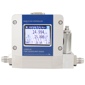 Small Coriolis flow meter/mass flow controller
Coriolis principle small flow meter/flow controller, Best accuracy mass flow meter for gas, liquid and steam. It can detect 40 g/h flow or even lower.
VIEW
Small Coriolis flow meter/mass flow controller
Coriolis principle small flow meter/flow controller, Best accuracy mass flow meter for gas, liquid and steam. It can detect 40 g/h flow or even lower.
VIEW
 High precision liquid flow meter-Coriolis flow meter
What is the Coriolis Flow Meter?When you want to measure the mass flowother than the volumetric consider using Coriolis flow meter. It uses theprinciple of inertia force on an object with reference to...
VIEW
High precision liquid flow meter-Coriolis flow meter
What is the Coriolis Flow Meter?When you want to measure the mass flowother than the volumetric consider using Coriolis flow meter. It uses theprinciple of inertia force on an object with reference to...
VIEW
 Liquid Mass flow meter
All kinds liquid measurement Density measurement as well Fuel, syrup, polymer, molasses Also, can measure corrosive liquid
VIEW
Liquid Mass flow meter
All kinds liquid measurement Density measurement as well Fuel, syrup, polymer, molasses Also, can measure corrosive liquid
VIEW
 Bent tube Coriolis flow meter
Smaller installation size. Max sensor size 10 inches. Profibus PA/HART/MODBUS. Better for high viscosity or slurry liquid.
VIEW
Bent tube Coriolis flow meter
Smaller installation size. Max sensor size 10 inches. Profibus PA/HART/MODBUS. Better for high viscosity or slurry liquid.
VIEW
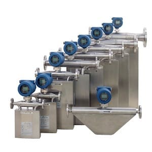
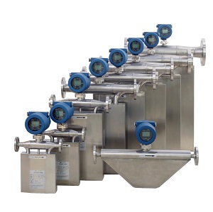
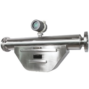 Large size Coriolis mass flow meter
Large size: 4 inch,5 inch, 6 inch, 8 inch, 10 inch,12 inch. Max flow range: 1000 ton/hour. Option with high pressure design. Direct mass flow crude oil, fuel and so on.
VIEW
Large size Coriolis mass flow meter
Large size: 4 inch,5 inch, 6 inch, 8 inch, 10 inch,12 inch. Max flow range: 1000 ton/hour. Option with high pressure design. Direct mass flow crude oil, fuel and so on.
VIEW
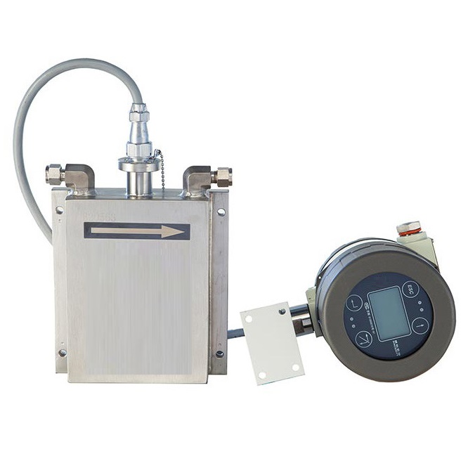
 Micro low flow Coriolis flow meter
Min flow 0-10 kg/hr Coriolis principle. ATEX approved. Suitable for low flow gas, liquid or steam.
VIEW
Micro low flow Coriolis flow meter
Min flow 0-10 kg/hr Coriolis principle. ATEX approved. Suitable for low flow gas, liquid or steam.
VIEW
 Coriolis Mass Flow Meter
Direct mass flow measurement. High accuracy: 0.1 %~0.2%. Also measure density, temperature, pressure. For all fluids measurement.
VIEW
Coriolis Mass Flow Meter
Direct mass flow measurement. High accuracy: 0.1 %~0.2%. Also measure density, temperature, pressure. For all fluids measurement.
VIEW