
English

The oval gear flowmeter must be installed at an appropriate location, with strict attention to the following critical requirements:
1) The surrounding temperature and humidity should comply with the oval gear flow meter manufacturer's regulations, with a general temperature of -10 (-15)~40 (50) °C and humidity of 10%~90% .
2) Direct sunlight in summer can cause temperatures to rise; Places close to radiant heat can also cause an increase in temperature. Sunshade or insulation measures should be taken in such places.
3) Non-weatherproof instruments (non-dustproof/waterproof models) must be installed away from corrosive atmospheres or humid environments. Condensation formed by diurnal temperature fluctuations, combined with corrosive gases, can damage critical components such as the integrator's reduction gears. When unavoidable installation in such conditions is necessary, maintain a slight positive pressure inside the enclosure through a clean air purge system.
4) The installation location must be free from excessive vibration and mechanical shock. Areas with rotating equipment or heavy machinery should be avoided unless proper vibration isolation measures are implemented.
5) There should be sufficient space for installation and daily maintenance.
The oval gear flow meter shall be installed with perfect leveling and vertical alignment. The rotor shaft shall maintain parallel to ground level, except for vertically-oriented rotor shaft designs; other models shall be installed horizontally as specified in the operation manual. Refer to Figure 1 for typical installation schematic.
For reverse flow direction applications, the flowmeter and filter positions shall be swapped from the illustrated configuration. Adequate clearance shall be provided for filter screen removal and cleaning. In vertical installations, the PDF shall be mounted on a bypass line to prevent debris ingress from upstream piping.

The oval gear flowmeter shall be isolated from pipeline stresses including thermal expansion/contraction, deformation, and vibration. Improper valve/piping design-induced vibration shall be prevented, with particular attention to avoiding resonance conditions. Installation shall avoid mechanical stress caused by non-parallel flange faces, excessive flange gap distance, pipe misalignment and other improper piping configurations.
For oval gear flow meter with integrated pressure housings and measuring chambers, excessive installation stress may cause housing deformation, affect measurement accuracy degradation and even jam movable measuring components.
Oval gear flow meter feature minimal clearances between the measuring chamber and moving components. Particulate contamination in the fluid may cause component seizure and premature wear. A strainer shall be installed upstream with routine cleaning maintenance. For gas measurement, install protective devices when required, such as sediment traps or moisture absorbers.For liquid flow measurement applications, gas ingress into the piping system must be prevented. When necessary, a gas-liquid separator shall be installed upstream of the measurement device.

While there are successful cases of installation on pump suction lines, the oval gear flow meters shall be installed on the pump discharge side as standard practice. Pulsating and surge flows can damage oval gear flow sensors. Ideal flow sources include centrifugal pumps and elevated head tanks.For applications involving reciprocating pumps or piping systems susceptible to overpressure surges (including water hammer effects), protective devices such as pulsation dampeners, expansion chambers and pressure relief valves shall be installed.
Overspeed operation of a elliptical gear flowmeter may cause irreversible damage. In systems where overload flow conditions may occur. Protective devices such as restriction orifice, constant flow valve and flow controller shall be installed downstream.
Newly installed pipelines must be cleaned before operation, and subsequent flushing with actual fluid is often required to remove residual welding slag, scale, and other debris.This process should close the shut-off valves at both the inlet and outlet of the flowmeter to divert fluid through the bypass line.
If no bypass line is available, replace the flowmeter with a short pipe section temporarily.
When switching the fluid flow from the bypass pipe to the instrument, the opening and closing sequence must be correct, and operations should be performed slowly—especially on high-temperature and high-pressure pipelines. As shown in Figure 2, the steps for activation are as follows:
For deactivation, follow the reverse sequence and actions.
After startup, use the lowest-position pointer or numeral wheel along with a stopwatch to confirm that excessive flow is not occurring. The optimal flow rate should be maintained at (70–80)% of the maximum flow rate to ensure the instrument's service life.

Figure 2 Bypass Pipe Switching Sequence
The filter screen is most susceptible to damage during the initial startup of a new pipeline. After trial operation, promptly inspect whether the screen remains intact. Additionally, when the filter screen is clean and free of contaminants, record the pressure drop at normal flow rates. This parameter eliminates the need for future disassembly to check for clogging—instead, the extent of pressure drop increase can be used to determine whether cleaning is required.

For high-viscosity liquids flow measurement , heating is typically required to ensure flowability. When the elliptical gear flowmeter is shut down, the internal liquid cools and thickens. Before restarting, it must be reheated to reduce viscosity before allowing flow through the instrument. Otherwise, the thickened liquid may jam the moving measurement components, leading to instrument damage.

(4) Replace bearings, drive gears or rotors; install new flowmeter if damage is irreparable.


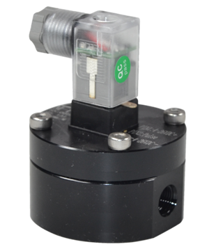
 Pulse Output positive displacement flow meter
NPN or PNP pulse output Explosion Proof pulse High accuracy ±0.5% or better Viscous liquid ready
VIEW
Pulse Output positive displacement flow meter
NPN or PNP pulse output Explosion Proof pulse High accuracy ±0.5% or better Viscous liquid ready
VIEW
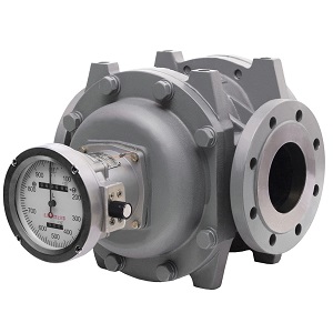 Liquid roots flow meter
Aluminum Construction, Lightweight Rotary Lobe Flowmeter For Gasoline, Diesel and fuel oil Mechanical or Electronic Display
VIEW
Liquid roots flow meter
Aluminum Construction, Lightweight Rotary Lobe Flowmeter For Gasoline, Diesel and fuel oil Mechanical or Electronic Display
VIEW
 Flow meters for low flow applications
A low flow flowmeter is a specialized flow measurement instrument designed to accurately measure and monitor very low flow rates of fluids or gases, typically expressed in units such as SCCM (standard...
VIEW
Flow meters for low flow applications
A low flow flowmeter is a specialized flow measurement instrument designed to accurately measure and monitor very low flow rates of fluids or gases, typically expressed in units such as SCCM (standard...
VIEW
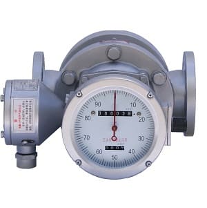
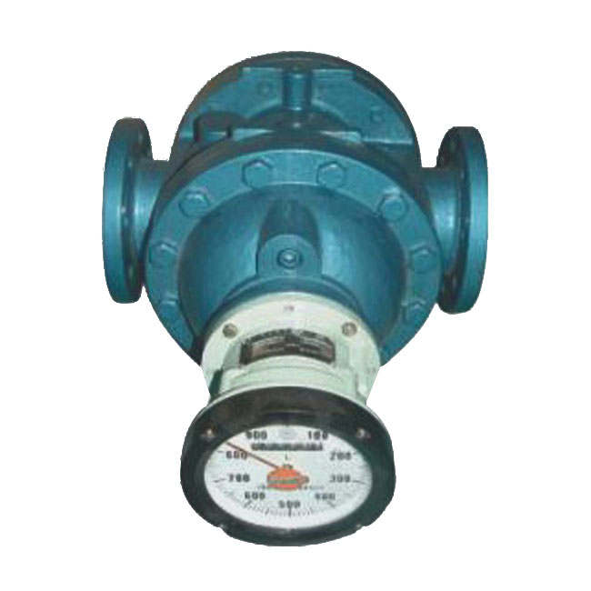
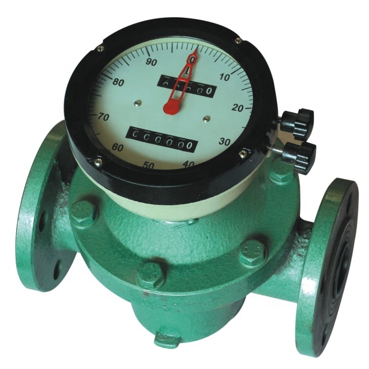 Oval gear flow meter
Oval gear flowmeter is a kind of positive displacement flowmeter for fuel,diesel,crude oil,alcohol,lubricating oil flow measurement.
VIEW
Oval gear flow meter
Oval gear flowmeter is a kind of positive displacement flowmeter for fuel,diesel,crude oil,alcohol,lubricating oil flow measurement.
VIEW
 Helical gear flow meters/Bi rotor flowmeter
Positive displacement flow meter A couple of helical gear Low noise and No pulsation High accuracy For crude oil, fuel or high viscosity liquid
VIEW
Helical gear flow meters/Bi rotor flowmeter
Positive displacement flow meter A couple of helical gear Low noise and No pulsation High accuracy For crude oil, fuel or high viscosity liquid
VIEW
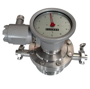 Sanitary Oval gear flow meter
Hygienic and sanitary oval gear style flow meter is kind of positive displacement (PD) flow meter which can be used in dairy,food processing industry or bio-technology industry; it has two rotating ov...
VIEW
Sanitary Oval gear flow meter
Hygienic and sanitary oval gear style flow meter is kind of positive displacement (PD) flow meter which can be used in dairy,food processing industry or bio-technology industry; it has two rotating ov...
VIEW